
Prescott New Instructions
Software Developer's Guide
252490-004
January 2004

Revision History
INFORMATION IN THIS DOCUMENT IS PROVIDED IN CONNECTION WITH INTEL PRODUCTS. NO LICENSE,
EXPRESS OR IMPLIED, BY ESTOPPEL OR OTHERWISE, TO ANY INTELLECTUAL PROPERTY RIGHTS IS GRANTED
BY THIS DOCUMENT. EXCEPT AS PROVIDED IN INTEL'S TERMS AND CONDITIONS OF SALE FOR SUCH
PRODUCTS, INTEL ASSUMES NO LIABILITY WHATSOEVER, AND INTEL DISCLAIMS ANY EXPRESS OR IMPLIED
WARRANTY, RELATING TO SALE AND/OR USE OF INTEL PRODUCTS INCLUDING LIABILITY OR WARRANTIES
RELATING TO FITNESS FOR A PARTICULAR PURPOSE, MERCHANTABILITY, OR INFRINGEMENT OF ANY PATENT,
COPYRIGHT OR OTHER INTELLECTUAL PROPERTY RIGHT. INTEL PRODUCTS ARE NOT INTENDED FOR USE IN
MEDICAL, LIFE SAVING, OR LIFE SUSTAINING APPLICATIONS.
Intel may make changes to specifications and product descriptions at any time, without notice.
Developers must not rely on the absence or characteristics of any features or instructions marked "reserved" or "undefined."
Improper use of reserved or undefined features or instructions may cause unpredictable behavior or failure in developer's
software code when running on an Intel processor. Intel reserves these features or instructions for future definition and shall
have no responsibility whatsoever for conflicts or incompatibilities arising from their unauthorized use.
The Intel® processors may contain design defects or errors known as errata. Current characterized errata are available on
request.
Intel, Pentium, Intel Xeon, Intel Pentium III Xeon, Intel NetBurst, MMX, and Celeron, are trademarks or registered
trademarks of Intel Corporation and its subsidiaries in the United States and other countries.
Prescott is a code name that is used internally within Intel to identify products that are in development and not yet publicly
announced for release. Customers, licensees and other third parties are not authorized by Intel to use code names in
advertising, promotion or marketing of any product or services and any such use of Intel's internal code names is at the sole
risk of the user.
Hyper-Threading Technology requires a computer system with an Intel® Pentium® 4 processor supporting HT Technology
and a Hyper-Threading Technology enabled chipset, BIOS and operating system. Performance will vary depending on the
specific hardware and software you use. See http://www.intel.com/info/hyperthreading/ for more information including
details on which processors support HT Technology.
*Other names and brands may be claimed as the property of others.
Contact your local Intel sales office or your distributor to obtain the latest specifications and before placing your product
order.
Copies of documents which have an ordering number and are referenced in this document, or other Intel literature, may be
obtained from:
Intel Corporation
P.O. Box 5937
Denver, CO 80217-9808
or call 1-800-548-4725
or visit Intel's website at http://www.intel.com
Copyright © 2003-2004 Intel Corporation
.002
Table 2-1: Revised function 4H and 80000006H.
Section 2.1.2: Corrected extended family encoding display algorithm.
Table 2.5: Revised for consistency.
Figure 2.6: Added clarification.
Section 4.3.1: Corrected LDDQU type usage.
.003
Included intrinsics.
Included opcodes.
Corrected comment in Example 4.1.
.004
Corrects errors and omissions in description of instructions. Adds some new information.
Provides encoding information (see Appendix A).
iii
CONTENTS
PAGE

CONTENTS
iv
PAGE
v
FIGURES
PAGE
TABLE OF FIGURES
vi
PAGE
vii
TABLES
PAGE
TABLE OF TABLES
viii
PAGE
1-1
CHAPTER 1
NEXT GENERATION
INTEL
®
PROCESSOR OVERVIEW
1.1.
KEY FEATURES
Prescott is the code name for a new generation of IA32 processors. The technology incorporates
an enhanced Intel
®
NetBurst
®
microarchitecture. Other features include:
·
Support for Hyper-Threading (HT) Technology
1
·
Prescott New Instructions (PNI)
·
Deeper pipelining to enable higher frequency
·
A High-speed System Bus
Prescott improves on the Pentium
®
4 processor's hyper-pipelined technology to achieve even
higher clock rates than previous generations of Pentium 4 processors. At the same time, the new
processor has larger first-level and second-level caches, more store buffers, write-combining
buffers.
Support for PNI does not require new OS support for saving and restoring the new state during
a context switch, beyond that provided for Streaming SIMD Extensions. The instruction set is
compatible with all software written for Intel
®
architecture microprocessors.
1.2.
HYPER-THREADING TECHNOLOGY
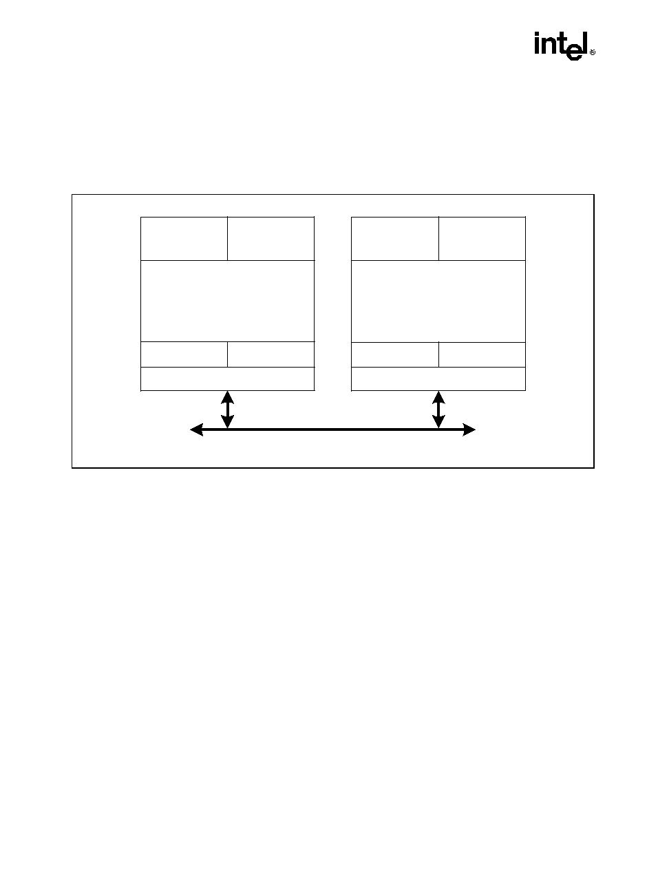
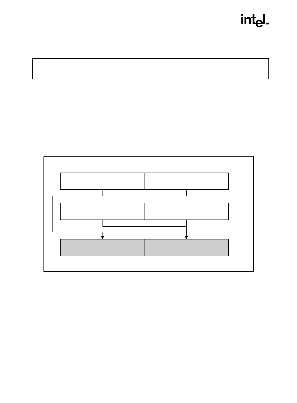
Hyper-Threading Technology (HT Technology) makes a single physical processor appear as
multiple logical processors by running two threads simultaneously. This is accomplished by
duplicating the architecture state for each logical processor in the physical processor and sharing
the physical execution resources within a physical processor package between the logical
processors. Each logical processor maintains a complete architecture state (see Figure 1-1).
From a software or architecture perspective, this means operating systems and user programs
can schedule processes or threads to logical processors as they would on conventional physical
processors. From a microarchitectural perspective, this means that instructions from both logical
processors will persist and execute simultaneously on shared execution resources.
1. Hyper-Threading Technology requires a computer system with an Intel
®
Pentium
®
4 processor support-
ing HT Technology and a Hyper-Threading Technology enabled chipset, BIOS and operating system.
Performance will vary depending on the specific hardware and software you use. See
http://www.intel.com/info/hyperthreading/ for more information including details on which processors sup-
port HT Technology.
1-2
NEXT GENERATION INTEL® PROCESSOR OVERVIEW
HT Technology is available across the server, workstation and desktop segments in the IA-32
processor family. Software detects support for HT Technology in IA-32 processors by using the
CPUID instruction. All HT Technology configurations require a chipset and BIOS that utilize
the technology, and an operating system that includes optimizations for HT Technology. See
www.intel.com/info/hyperthreading for more information.
A system with processors that are HT Technology capable appear to the operating system and
application software as having twice the number of processors as the number of physical proces-
sors. Operating systems manage logical processors as they do physical processors, scheduling
run-able tasks or threads to logical processors.
Processors supporting HT Technology deliver higher performance than a comparable physical
processor that do not support HT technology. However, HT Technology does not deliver the
same performance as a multiprocessor system with two physical processors.
1.3.
ENHANCED CPUID CAPABILITIES
The CPUID instruction has been enhanced to support the following new features:
·
PNI, including MONITOR-MWAIT support
·
Debug Trace Store Qualification
·
Enhanced Intel
®
SpeedStep
®
technology (uses model-specific registers on the processor)
Figure 1-1. Two Logical Processors in One Physical Package
OM15631
Bus Interface
Execution Engine
Architectural
State
Architectural
State
Local APIC
Local APIC
System Bus
Execution Engine
Architectural
State
Architectural
State
Local APIC
Local APIC
Bus Interface
1-3
NEXT GENERATION INTEL® PROCESSOR OVERVIEW
The behavior of the CPUID instruction has not changed (although more values are returned).
The instruction provides a wealth of information that are organized into pages or leaves; leaves
are queried by loading different values in EAX and then executing the instruction.
1.4.
PRESCOTT NEW INSTRUCTIONS
PNI consists of 13 new instructions that accelerate performance of Streaming SIMD Extensions
technology, Streaming SIMD Extensions 2 technology, and x87-FP math capabilities. The new
technology is compatible with existing software written for Intel architecture microprocessors
and existing software should continue to run correctly, without modification, on microproces-
sors that incorporate these extensions.
The new instructions are summarized in the following sections.
1.4.1.
One Instruction That Improves x87-FP Integer Conversion
FISTTP (Store Integer and Pop from x87-FP with Truncation) behaves like the FISTP instruc-
tion but uses truncation, irrespective of the rounding mode specified in the floating-point control
word (FCW). The instruction converts the top of stack (ST0) to integer with rounding to truncate
and pop the stack.
FISTTP is available in three precisions: short integer (word or 16-bit), integer (double word or
32-bit), and long integer (64-bit). With FISTTP, applications no longer need to change the FCW
when truncation is desired. This instruction is the only x87-FP instruction in PNI.
1.4.2.
Three Instructions Enhance LOAD/MOVE/DUPLICATE
Performance
MOVSHDUP loads/moves 128-bits, duplicating the second and fourth 32-bit data elements.
·
MOVSHDUP OperandA OperandB
·
OperandA (128 bits, four data elements): 3
a
, 2
a
, 1
a
, 0
a
·
OperandB (128 bits, four data elements): 3
b
, 2
b
, 1
b
, 0
b
·
Result (stored in OperandA): 3
b
, 3
b
, 1
b
, 1
b
MOVSLDUP loads/moves 128-bits, duplicating the first and third 32-bit data elements.
·
MOVSLDUP OperandA OperandB
·
OperandA (128 bits, four data elements): 3
a
, 2
a
, 1
a
, 0
a
·
OperandB (128 bits, four data elements): 3
b
, 2
b
, 1
b
, 0
b
·
Result (stored in OperandA): 2
b
, 2
b
, 0
b
, 0
b
1-4
NEXT GENERATION INTEL® PROCESSOR OVERVIEW
MOVDDUP loads/moves 64-bits (bits[63-0] if the source is a register) and returns the same 64
bits in both the lower and upper halves of the 128-bit result register. This duplicates the 64 bits
from the source.
·
MOVDDUP OperandA OperandB
·
OperandA (128 bits, two data elements): 1
a
, 0
a
·
OperandB (64 bits, one data element): 0
b
·
Result (stored in OperandA): 0
b
, 0
b
1.4.3.
One Instruction Provides Specialized 128-bit Unaligned
Data Load
LDDQU is a special 128-bit unaligned load designed to avoid cache line splits. If the address of
the load is aligned on a 16-byte boundary, LDQQU loads the 16 bytes requested. If the address
of the load is not aligned on a 16-byte boundary, LDDQU loads a 32-byte block starting at the
16-byte aligned address immediately below the load request. It then extracts the requested 16
bytes.
The instruction provides significant performance improvement on 128-bit unaligned memory
accesses at the cost of some usage model restrictions.
1.4.4.
Two Instructions Provide Packed Addition/Subtraction
ADDSUBPS has two 128-bit operands. The instruction performs single-precision addition on
the second and fourth pairs of 32-bit data elements within the operands; and single-precision
subtraction on the first and third pairs. This instruction is effective at evaluating complex prod-
ucts on packed single-precision data.
·
ADDSUBPS OperandA OperandB
·
OperandA (128 bits, four data elements): 3
a
, 2
a
, 1
a
, 0
a
·
OperandB (128 bits, four data elements): 3
b
, 2
b
, 1
b
, 0
b
·
Result (stored in OperandA): 3
a
+3
b
, 2
a
-2
b
, 1
a
+1
b
, 0
a
-0
b
ADDSUBPD has two 128-bit operands. The instruction performs double-precision addition on
the second pair of quadwords, and double-precision subtraction on the first pair. This instruction
is useful when evaluating complex products on packed double-precision data.
·
ADDSUBPD OperandA OperandB
·
OperandA (128 bits, two data elements): 1
a
, 0
a
·
OperandB (128 bits, two data elements): 1
b
, 0
b
·
Result (stored in OperandA): 1
a
+1
b
, 0
a
-0
b
1-5
NEXT GENERATION INTEL® PROCESSOR OVERVIEW
1.4.5.
Four Instructions Provide Horizontal Addition/Subtraction
Most SIMD instructions operate vertically. This means that the result in position i of the result
is a function of the elements in position i of both operands. Horizontal addition/subtraction oper-
ates horizontally. This means that contiguous data elements from the same operand are used to
produce a result data element.
HADDPS performs a single-precision addition on contiguous data elements. The first data
element of the result is obtained by adding the first and second elements of the first operand; the
second element by adding the third and fourth elements of the first operand; the third by adding
the first and second elements of the second operand; and the fourth by adding the third and
fourth elements of the second operand.
·
HADDPS OperandA OperandB
·
OperandA (128 bits, four data elements): 3
a
, 2
a
, 1
a
, 0
a
·
OperandB (128 bits, four data elements): 3
b
, 2
b
, 1
b
, 0
b
·
Result (Stored in OperandA): 3
b
+2
b
, 1
b
+0
b
, 3
a
+2
a
, 1
a
+0
a
HSUBPS performs a single-precision subtraction on contiguous data elements. The first data
element of the result is obtained by subtracting the second element of the first operand from the
first element of the first operand; the second element by subtracting the fourth element of the first
operand from the third element of the first operand; the third by subtracting the second element
of the second operand from the first element of the second operand; and the fourth by subtracting
the fourth element of the second operand from the third element of the second operand.
·
HSUBPS OperandA OperandB
·
OperandA (128 bits, four data elements): 3
a
, 2
a,
1
a
, 0
a
·
OperandB (128 bits, four data elements): 3
b
, 2
b
, 1
b
, 0
b
·
Result (Stored in OperandA): 2
b
-3
b
, 0
b
-1
b
, 2
a
-3
a
, 0
a
-1
a
HADDPD performs a double-precision addition on contiguous data elements. The first data
element of the result is obtained by adding the first and second elements of the first operand; the
second element by adding the first and second elements of the second operand.
·
HADDPD OperandA OperandB
·
OperandA (128 bits, two data elements): 1
a
, 0
a
·
OperandB (128 bits, two data elements): 1
b
, 0
b
·
Result (Stored in OperandA): 1
b
+0
b
, 1
a
+0
a
HSUBPD performs a double-precision subtraction on contiguous data elements. The first data
element of the result is obtained by subtracting the second element of the first operand from the
first element of the first operand; the second element by subtracting the second element of the
second operand from the first element of the second operand.
·
HSUBPD OperandA OperandB
·
OperandA (128 bits, two data elements): 1
a
, 0
a
1-6
NEXT GENERATION INTEL® PROCESSOR OVERVIEW
·
OperandB (128 bits, two data elements): 1
b
, 0
b
·
Result (Stored in OperandA): 0
b
-1
b
, 0
a
-1
a
1.4.6.
Two Instructions Improve Synchronization Between
Agents
MONITOR sets up an address range used to monitor write-back stores.
MWAIT enables a logical processor to enter into an optimized state while waiting for a write-
back store to the address range set up by the MONITOR instruction.
Support for MONITOR/MWAIT is indicated by the CPUID MONITOR/MWAIT Software need
not check for support of SSE in order to use the MONITOR/MWAIT.

2-1
CHAPTER 2
CPUID EXTENSIONS
2.1.
VALUES RETURNED USING CPUID
CPUID instruction and feature-identification bits have been added for software to identify the
features offered by Prescott New Instructions. Table 2-1 shows the value in EAX before a call
to CPUID and the value returned.
For impacted areas, note the bold type.
Table 2-1. Information Returned by CPUID Instruction
Initial EAX
Value
Information Provided about the Processor
Basic CPUID Information
0H
EAX
EBX
ECX
EDX
Maximum Input Value for Basic CPUID Information (see Table 2-2)
"Genu"
"ntel"
"ineI"
01H
EAX
EBX
ECX
EDX
Version Information: Type, Family, Model, and Stepping ID (see Figure
2-1)
Bits 7-0: Brand Index
Bits 15-8: CLFLUSH line size (Value
8 = cache line size in bytes)
Bits 23-16: Number of logical processors per physical processor; two for
the Pentium 4 processor supporting Hyper-Threading Technology
Bits 31-24: Local APIC ID
Extended Feature Information (see Figure 2-2 and Table 2-4)
Feature Information (see Figure 2-3 and Table 2-5)
02H
EAX
EBX
ECX
EDX
Cache and TLB Information (see Table 2-6)
Cache and TLB Information
Cache and TLB Information
Cache and TLB Information
03H
EAX
EBX
ECX
EDX
Reserved.
Reserved.
Bits 00-31 of 96 bit processor serial number. (Available in Pentium III
processor only; otherwise, the value in this register is reserved.)
Bits 32-63 of 96 bit processor serial number. (Available in Pentium III
processor only; otherwise, the value in this register is reserved.)
NOTE: Processor serial number (PSN) is not supported in the Pentium 4
processor or later. On all models, use the PSN flag (returned using CPUID)
to check for PSN support before accessing the feature. See AP-485, Intel
Processor Identification and the CPUID Instruction (Order Number 241618)
for more information on PSN.

2-2
CPUID EXTENSIONS
04H
EAX
EBX
ECX
Deterministic Cache Parameters Leaf
Bits 4-0: Cache Type**
Bits 7-5: Cache Level (starts at 1)
Bits 8: Self Initializing cache level (does not need SW initialization)
Bits 9: Fully Associative cache
Bits 13-10: Reserved
Bits 25-14: Number of threads sharing this cache*
Bits 31-26: Number of processor cores on this die (Multicore)*
Bits 11-00: L = System Coherency Line Size*
Bits 21-12: P = Physical Line partitions*
Bits 31-22: W = Ways of associativity*
Bits 31-00: S = Number of Sets*
EDX
Reserved = 0
*Add one to the value in the register file to get the number. For
example, the number of processor cores is EAX[31:26]+1.
** Cache Types fields
0 = Null - No more caches
1 = Data Cache
2 = Instruction Cache
3 = Unified Cache
4-31 = Reserved
NOTE: CPUID leaves > 3 < 80000000 are only visible when
IA32_CR_MISC_ENABLES.BOOT_NT4 (bit 22) is clear (Default)
5H
EAX
EBX
ECX
EDX
MONITOR/MWAIT Leaf
Bits 15-00: Smallest monitor-line size in bytes (default is processor's
monitor granularity)
Bits 31-16: Reserved = 0
Bits 15-00: Largest monitor-line size in bytes (default is processor's
monitor granularity)
Bits 31-16: Reserved = 0
Reserved = 0
Reserved = 0
Extended Function CPUID Information
80000000H
EAX
EBX
ECX
EDX
Maximum Input Value for Extended Function CPUID Information (see
Table 2-2).
Reserved
Reserved
Reserved
80000001H
EAX
EBX
ECX
EDX
Extended Processor Signature and Extended Feature Bits. (Currently
Reserved
Reserved
Reserved
Reserved
Table 2-1. Information Returned by CPUID Instruction (Contd.)
Initial EAX
Value
Information Provided about the Processor

2-3
CPUID EXTENSIONS
INPUT EAX = 0: Returns CPUID's Highest Value for Basic Processor Information
and the Vendor Identification String
When CPUID executes with EAX set to 0, the processor returns the highest value the CPUID
recognizes for returning basic processor information. The value is returned in the EAX register
(see Table 2-2) and is processor specific.
A vendor identification string is also returned in EBX, EDX, and ECX. For Intel processors, the
string is "GenuineIntel" and is expressed:
EBX
756e6547h (* "Genu", with G in the low nibble of BL *)
EDX
49656e69h (* "ineI", with i in the low nibble of DL *)
ECX
6c65746eh (* "ntel", with n in the low nibble of CL *)
80000002H
EAX
EBX
ECX
EDX
Processor Brand String
Processor Brand String Continued
Processor Brand String Continued
Processor Brand String Continued
80000003H
EAX
EBX
ECX
EDX
Processor Brand String Continued
Processor Brand String Continued
Processor Brand String Continued
Processor Brand String Continued
80000004H
EAX
EBX
ECX
EDX
Processor Brand String Continued
Processor Brand String Continued
Processor Brand String Continued
Processor Brand String Continued
80000005H
EAX
EBX
ECX
EDX
Reserved = 0
Reserved = 0
Reserved = 0
Reserved = 0
80000006H
EAX
EBX
ECX
EDX
Reserved = 0
Reserved = 0
Bits 0-7: Cache Line Size
Bits 15-12: L2 Associativity
Bits 31-16: Cache size in 1K units
Reserved = 0
80000007H
EAX
EBX
ECX
EDX
Reserved = 0
Reserved = 0
Reserved = 0
Reserved = 0
80000008H
EAX
EBX
ECX
EDX
Reserved = 0
Reserved = 0
Reserved = 0
Reserved = 0
Table 2-1. Information Returned by CPUID Instruction (Contd.)
Initial EAX
Value
Information Provided about the Processor

2-4
CPUID EXTENSIONS
IINPUT EAX = 80000000H: Returns CPUID's Highest Value for Extended Proces-
sor Information
When CPUID executes with EAX set to 0, the processor returns the highest value the processor
recognizes for returning extended processor information. The value is returned in the EAX
register (see Table 2-2) and is processor specific.
INPUT EAX = 1: Returns Model, Family and Stepping Information
When CPUID executes with EAX set to 1, version information is returned in EAX (see Figure
2-1). For example: model, family, and processor type for the first processor in the Intel Pentium
4 family is returned as follows:
·
Model--0000B
·
Family--1111B
·
Processor Type--00B
See Table 2-3 for available processor type values. Stepping IDs are provided as needed.
Table 2-2. Highest CPUID Source Operand for IA-32 Processors
IA-32 Processors
Highest Value in EAX
Basic Information
Extended Function Information
Earlier Intel486 Processors
CPUID Not Implemented
CPUID Not Implemented
Later Intel486 Processors and
Pentium Processors
01H
Not Implemented
Pentium Pro and Pentium II
Processors, Intel
®
CeleronTM
Processors
02H
Not Implemented
Pentium III Processors
03H
Not Implemented
Pentium 4 Processors
02H
80000004H
Intel Xeon Processors
02H
80000004H
Pentium M Processor
02H
80000004H
Pentium 4 Processor supporting
Hyper-Threading Technology
05H
80000008H
2-5
CPUID EXTENSIONS
NOTE
See AP-485, Intel Processor Identification and the CPUID Instruction (Order
Number 241618) and Chapter 13 in the IA-32 Intel Architecture Software
Developer's Manual, Volume 1, for information on identifying earlier IA-32
processors.
The Extended Family ID and Extended Model ID need be examined only if the Family ID
reaches 0FH. Always display processor information as a combination of family, model and step-
ping.
Integrate the ID fields into a display as:
Displayed family = ((Extended Family ID(4-bits) << 4)) (8-bits)
+ Family ID (4-bits zero extended to 8-bits)
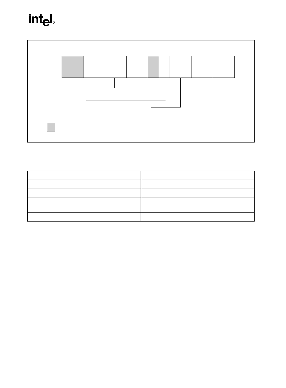
Figure 2-1. Version Information Returned by CPUID in EAX
Table 2-3. Processor Type Field
Type
Encoding
Original OEM Processor
00B
Intel
®
OverDrive
®
Processor
01B
Dual processor (not applicable to Intel486
processors)
10B
Intel reserved.
11B
OM16525
Processor Type
0
3
4
7
8
11
12
13
14
15
16
19
20
27
28
31
EAX
Family (0FH for the Pentium 4 Processor Family
Model
Extended
Family ID
Extended
Model ID
Family
ID
Model
Stepping
ID
Extended Family ID (0)
Extended Model ID (0)
Reserved
2-6
CPUID EXTENSIONS
Compute the displayed model from the Model ID and the Extended Model ID as:
Displayed Model = ((Extended Model ID (4-bits) << 4))(8-bits)
+ Model (4-bits zero extended to 8-bits)
INPUT EAX = 1: Returns Additional Information in EBX
When CPUID executes with EAX set to 1, additional information is returned to the EBX
register:
·
Brand index (low byte of EBX) -- this number provides an entry into a brand string table
that contains brand strings for IA-32 processors. More information about this field is
provided later in this section.
·
CLFLUSH instruction cache line size (second byte of EBX) -- this number indicates the
size of the cache line flushed with CLFLUSH instruction in 8-byte increments. This field
was introduced in the Pentium 4 processor.
·
Local APIC ID (high byte of EBX) -- this number is the 8-bit ID that is assigned to the
local APIC on the processor during power up. This field was introduced in the Pentium 4
processor.
INPUT EAX = 1: Returns Feature Information in ECX and EDX
When CPUID executes with EAX set to 1, feature information is returned in ECX and EDX.
·
·
For all feature flags, a 1 indicates that the feature is supported. Use Intel to properly interpret
feature flags.
NOTE
Software must confirm that a processor feature is present using feature flags
returned by CPUID prior to using the feature. Software should not depend on
future offerings retaining all features.
2-7
CPUID EXTENSIONS
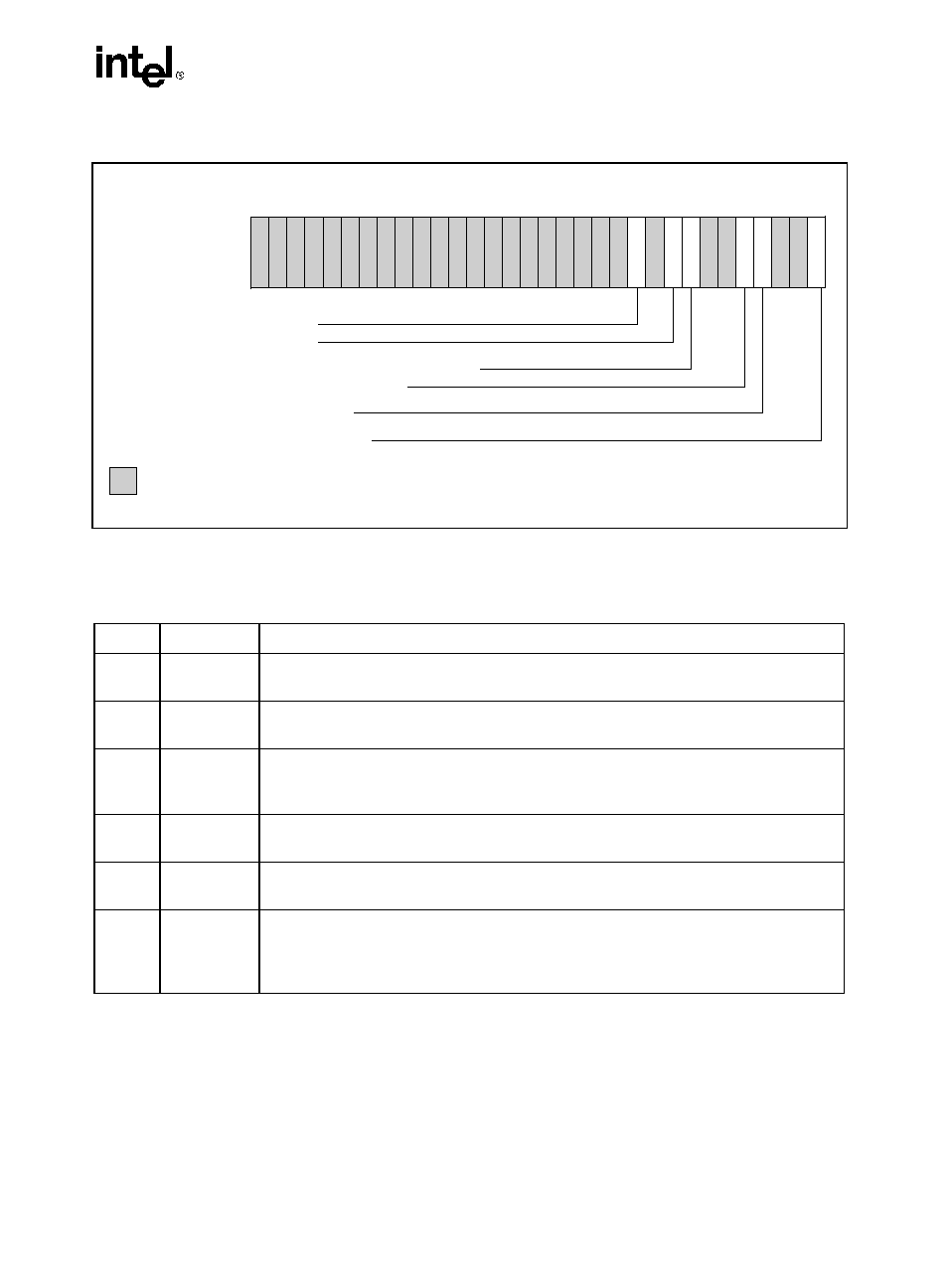
Figure 2-2. Extended Feature Information Returned in the ECX Register
Table 2-4. More on Extended Feature Information Returned in the ECX Register
Bit #
Mnemonic
Description
0
PNI
Prescott New Instructions (PNI). A value of 1 indicates the processor
supports this technology.
3
MONITOR
MONITOR/MWAIT. A value of 1 indicates the processor supports this
feature.
4 DS-CPL
CPL Qualified Debug Store. A value of 1 indicates the processor supports the
extensions to the Debug Store feature to allow for branch message storage
qualified by CPL.
7
EST
Enhanced Intel SpeedStep technology. A value of 1 indicates that the
processor supports this technology.
8 TM2 Thermal Monitor 2. A value of 1 indicates whether the processor supports this
technology.
10
CNXT-ID
L1 Context ID. A value of 1 indicates the L1 data cache mode can be set to
either adaptive mode or shared mode. A value of 0 indicates this feature is not
supported. See definition of the IA32_MISC_ENABLE MSR Bit 24 (L1 Data
Cache Context Mode) for details.
OM16524a
CNXT-ID -- L1 Context ID
0
1
2
3
4
5
6
7
8
9
10
11
12
13
14
15
16
17
18
19
20
21
22
23
24
25
26
27
28
29
30
31
ECX
TM2 -- Thermal Monitor 2
EST -- Enhanced Intel SpeedStep® technology
DS-CPL -- CPL Qualified Debug Store
MONITOR -- MONITOR/MWAIT
PNI -- Prescott New Instructions
Reserved
2-8
CPUID EXTENSIONS
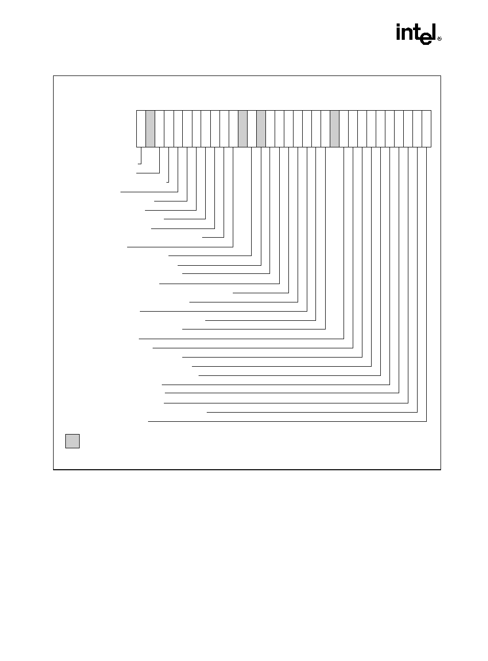
Figure 2-3. Feature Information Returned in the EDX Register
OM16523
PBEPend. Brk. EN.
0
1
2
3
4
5
6
7
8
9
10
11
12
13
14
15
16
17
18
19
20
21
22
23
24
25
26
27
28
29
30
31
EDX
TMTherm. Monitor
HTTHyper-Threading Tech.
SSSelf Snoop
SSE2SSE2 Extensions
SSESSE Extensions
FXSRFXSAVE/FXRSTOR
MMXMMX Technology
ACPIThermal Monitor and Clock Ctrl
DSDebug Store
CLFSHCFLUSH instruction
PSNProcessor Serial Number
PSE-36 Page Size Extension
PATPage Attribute Table
CMOVConditional Move/Compare Instruction
MCAMachine Check Architecture
PGEPTE Global Bit
MTRRMemory Type Range Registers
SEPSYSENTER and SYSEXIT
APICAPIC on Chip
CX8CMPXCHG8B Inst.
MCEMachine Check Exception
PAEPhysical Address Extensions
MSRRDMSR and WRMSR Support
TSCTime Stamp Counter
PSEPage Size Extensions
DEDebugging Extensions
VMEVirtual-8086 Mode Enhancement
FPUx87 FPU on Chip
Reserved

2-9
CPUID EXTENSIONS
Table 2-5. More on Feature Information Returned in the EDX Register
Bit #
Mnemonic
Description
0 FPU
Floating Point Unit On-Chip. The processor contains an x87 FPU.
1 VME
Virtual 8086 Mode Enhancements. Virtual 8086 mode enhancements, including
CR4.VME for controlling the feature, CR4.PVI for protected mode virtual
interrupts, software interrupt indirection, expansion of the TSS with the software
indirection bitmap, and EFLAGS.VIF and EFLAGS.VIP flags.
2 DE
Debugging Extensions. Support for I/O breakpoints, including CR4.DE for
controlling the feature, and optional trapping of accesses to DR4 and DR5.
3 PSE
Page Size Extension. Large pages of size 4Mbyte are supported, including
CR4.PSE for controlling the feature, the defined dirty bit in PDE (Page Directory
Entries), optional reserved bit trapping in CR3, PDEs, and PTEs.
4 TSC
Time Stamp Counter. The RDTSC instruction is supported, including CR4.TSD
for controlling privilege.
5 MSR
Model Specific Registers RDMSR and WRMSR Instructions. The RDMSR and
WRMSR instructions are supported. Some of the MSRs are implementation
dependent.
6 PAE
Physical Address Extension.
Physical addresses greater than 32 bits are
supported: extended page table entry formats, an extra level in the page
translation tables is defined, 2 Mbyte pages are supported instead of 4 Mbyte
pages if PAE bit is 1. The actual number of address bits beyond 32 is not defined,
and is implementation specific.
7 MCE
Machine Check Exception. Exception 18 is defined for Machine Checks,
including CR4.MCE for controlling the feature. This feature does not define the
model-specific implementations of machine-check error logging, reporting, and
processor shutdowns. Machine Check exception handlers may have to depend on
processor version to do model specific processing of the exception, or test for the
presence of the Machine Check feature.
8 CX8
CMPXCHG8B Instruction. The compare-and-exchange 8 bytes (64 bits)
instruction is supported (implicitly locked and atomic).
9 APIC
APIC On-Chip. The processor contains an Advanced Programmable Interrupt
Controller (APIC), responding to memory mapped commands in the physical
address range FFFE0000H to FFFE0FFFH (by default - some processors permit
the APIC to be relocated).
10 Reserved Reserved
11
SEP
SYSENTER and SYSEXIT Instructions. The SYSENTER and SYSEXIT and
associated MSRs are supported.
12 MTRR
Memory Type Range Registers. MTRRs are supported. The MTRRcap MSR
contains feature bits that describe what memory types are supported, how many
variable MTRRs are supported, and whether fixed MTRRs are supported.
13 PGE
PTE Global Bit. The global bit in page directory entries (PDEs) and page table
entries (PTEs) is supported, indicating TLB entries that are common to different
processes and need not be flushed. The CR4.PGE bit controls this feature.

2-10
CPUID EXTENSIONS
14 MCA
Machine Check Architecture. The Machine Check Architecture, which provides
a compatible mechanism for error reporting in P6 family, Pentium 4, and Intel
Xeon processors, and future processors, is supported. The MCG_CAP MSR
contains feature bits describing how many banks of error reporting MSRs are
supported.
15 CMOV
Conditional Move Instructions. The conditional move instruction CMOV is
supported. In addition, if x87 FPU is present as indicated by the CPUID.FPU
feature bit, then the FCOMI and FCMOV instructions are supported
16 PAT
Page Attribute Table. Page Attribute Table is supported. This feature augments
the Memory Type Range Registers (MTRRs), allowing an operating system to
specify attributes of memory on a 4K granularity through a linear address.
17 PSE-36 36-Bit Page Size Extension. Extended 4-MByte pages that are capable of
addressing physical memory beyond 4 GBytes are supported. This feature
indicates that the upper four bits of the physical address of the 4-MByte page is
encoded by bits 13-16 of the page directory entry.
18 PSN
Processor Serial Number. The processor supports the 96-bit processor
identification number feature and the feature is enabled.
19 CLFSH
CLFLUSH Instruction. CLFLUSH Instruction is supported.
20
Reserved Reserved
21 DS
Debug Store. The processor supports the ability to write debug information into a
memory resident buffer. This feature is used by the branch trace store (BTS) and
precise event-based sampling (PEBS) facilities (see Chapter 15, Debugging and
Performance Monitoring, in the IA-32 Intel Architecture Software Developer's
Manual, Volume 3).
22 ACPI
Thermal Monitor and Software Controlled Clock Facilities. The processor
implements internal MSRs that allow processor temperature to be monitored and
processor performance to be modulated in predefined duty cycles under software
control.
23 MMX
Intel MMX Technology. The processor supports the Intel MMX technology.
24 FXSR
FXSAVE and FXRSTOR Instructions. The FXSAVE and FXRSTOR instructions
are supported for fast save and restore of the floating point context. Presence of
this bit also indicates that CR4.OSFXSR is available for an operating system to
indicate that it supports the FXSAVE and FXRSTOR instructions
25 SSE
SSE. The processor supports the SSE extensions.
26 SSE2
SSE2. The processor supports the SSE2 extensions.
27
SS
Self Snoop. The processor supports the management of conflicting memory
types by performing a snoop of its own cache structure for transactions issued to
the bus
Table 2-5. More on Feature Information Returned in the EDX Register (Contd.)
Bit #
Mnemonic
Description

2-11
CPUID EXTENSIONS
INPUT EAX = 2: Cache and TLB Information Returned in EAX, EBX, ECX, EDX
When CPUID executes with EAX set to 2, the processor returns information about the
processor's internal caches and TLBs in the EAX, EBX, ECX, and EDX registers.
The encoding is as follows:
·
The least-significant byte in register EAX (register AL) indicates the number of times the
CPUID instruction must be executed with an input value of 2 to get a complete description
of the processor's caches and TLBs. The first member of the family of Pentium 4
processors will return a 1.
·
The most significant bit (bit 31) of each register indicates whether the register contains
valid information (set to 0) or is reserved (set to 1).
·
If a register contains valid information, the information is contained in 1 byte descriptors.
Table 2-6 shows the encoding of these descriptors. Note that the order of descriptors in the
EAX, EBX, ECX, and EDX registers is not defined; that is, specific bytes are not
designated to contain descriptors for specific cache or TLB types. The descriptors may
appear in any order.
28
HTT
Hyper-Threading Technology. The processor supports Hyper-Threading
Technology.
29
TM
Thermal Monitor. The processor implements the thermal monitor automatic
thermal control circuitry (TCC).
30
Reserved
Reserved
31
PBE
Pending Break Enable. The processor supports the use of the FERR#/PBE# pin
when the processor is in the stop-clock state (STPCLK# is asserted) to signal the
processor that an interrupt is pending and that the processor should return to
normal operation to handle the interrupt. Bit 10 (PBE enable) in the
IA32_MISC_ENABLE MSR enables this capability.
Table 2-5. More on Feature Information Returned in the EDX Register (Contd.)
Bit #
Mnemonic
Description

2-12
CPUID EXTENSIONS
Table 2-6. Encoding of Cache and TLB Descriptors
Descriptor
Value
Cache or TLB Description
00H
Null descriptor
01H
Instruction TLB: 4K-Byte Pages, 4-way set associative, 32 entries
02H
Instruction TLB: 4M-Byte Pages, 4-way set associative, 2 entries
03H
Data TLB: 4K-Byte Pages, 4-way set associative, 64 entries
04H
Data TLB: 4M-Byte Pages, 4-way set associative, 8 entries
06H
1st-level instruction cache: 8K Bytes, 4-way set associative, 32 byte line size
08H
1st-level instruction cache: 16K Bytes, 4-way set associative, 32 byte line size
0AH
1st-level data cache: 8K Bytes, 2-way set associative, 32 byte line size
0CH
1st-level data cache: 16K Bytes, 4-way set associative, 32 byte line size
22H
3rd-level cache: 512K Bytes, 4-way set associative, 64 byte line size, 128 byte sector size
23H
3rd-level cache: 1M Bytes, 8-way set associative, 64 byte line size, 128 byte sector size
25H
3rd-level cache: 2M Bytes, 8-way set associative, 64 byte line size, 128 byte sector size
29H
3rd-level cache: 4M Bytes, 8-way set associative, 64 byte line size, 128 byte sector size
2CH
1st-level data cache: 32K Bytes, 8-way set associative, 64 byte line size
30H
1st-level instruction cache: 32K Bytes, 8-way set associative, 64 byte line size
40H
No 2nd-level cache or, if processor contains a valid 2nd-level cache, no 3rd-level cache
41H
2nd-level cache: 128K Bytes, 4-way set associative, 32 byte line size
42H
2nd-level cache: 256K Bytes, 4-way set associative, 32 byte line size
43H
2nd-level cache: 512K Bytes, 4-way set associative, 32 byte line size
44H
2nd-level cache: 1M Byte, 4-way set associative, 32 byte line size
45H
2nd-level cache: 2M Byte, 4-way set associative, 32 byte line size
50H
Instruction TLB: 4-KByte and 2-MByte or 4-MByte pages, 64 entries
51H
Instruction TLB: 4-KByte and 2-MByte or 4-MByte pages, 128 entries
52H
Instruction TLB: 4-KByte and 2-MByte or 4-MByte pages, 256 entries
5BH
Data TLB: 4-KByte and 4-MByte pages, 64 entries
5CH
Data TLB: 4-KByte and 4-MByte pages,128 entries
5DH
Data TLB: 4-KByte and 4-MByte pages,256 entries
60H
1st-level data cache: 16KB, 8-way set associative, 64 byte line size
66H
1st-level data cache: 8KB, 4-way set associative, 64 byte line size
67H
1st-level data cache: 16KB, 4-way set associative, 64 byte line size
68H
1st-level data cache: 32KB, 4-way set associative, 64 byte line size
70H
Trace cache: 12K-
µop, 8-way set associative

2-13
CPUID EXTENSIONS
Example 2-1. Example of Cache and TLB Interpretation
The first member of the family of Pentium 4 processors returns the following information about
caches and TLBs when the CPUID executes with an input value of 2:
EAX
66 5B 50 01H
EBX
0H
ECX
0H
EDX
00 7A 70 00H
Which means:
·
The least-significant byte (byte 0) of register EAX is set to 01H. This indicates that CPUID
needs to be executed once with an input value of 2 to retrieve complete information about
caches and TLBs.
·
The most-significant bit of all four registers (EAX, EBX, ECX, and EDX) is set to 0,
indicating that each register contains valid 1-byte descriptors.
·
Bytes 1, 2, and 3 of register EAX indicate that the processor has:
-- 50H - a 64-entry instruction TLB, for mapping 4-KByte and 2-MByte or 4-MByte
pages.
71H
Trace cache: 16K-
µop, 8-way set associative
72H
Trace cache: 32K-
µop, 8-way set associative
78H
2nd-level cache: 1M Byte, 8-way set associative, 64byte line size
79H
2nd-level cache: 128KB, 8-way set associative, 64 byte line size, 128 byte sector size
7AH
2nd-level cache: 256KB, 8-way set associative, 64 byte line size, 128 byte sector size
7BH
2nd-level cache: 512KB, 8-way set associative, 64 byte line size, 128 byte sector size
7CH
2nd-level cache: 1MB, 8-way set associative, 64 byte line size, 128 byte sector size
7DH
2nd-level cache: 2M Byte, 8-way set associative, 64byte line size
82H
2nd-level cache: 256K Byte, 8-way set associative, 32 byte line size
83H
2nd-level cache: 512K Byte, 8-way set associative, 32 byte line size
84H
2nd-level cache: 1M Byte, 8-way set associative, 32 byte line size
85H
2nd-level cache: 2M Byte, 8-way set associative, 32 byte line size
86H
2nd-level cache: 512K Byte, 4-way set associative, 64 byte line size
87H
2nd-level cache: 1M Byte, 8-way set associative, 64 byte line size
B0H
Instruction TLB: 4K-Byte Pages, 4-way set associative, 128 entries
B3H
Data TLB: 4K-Byte Pages, 4-way set associative, 128 entries
Table 2-6. Encoding of Cache and TLB Descriptors (Contd.)
Descriptor
Value
Cache or TLB Description
2-14
CPUID EXTENSIONS
-- 5BH - a 64-entry data TLB, for mapping 4-KByte and 4-MByte pages.
-- 66H - an 8-KByte 1st level data cache, 4-way set associative, with a 64-byte cache line
size.
·
The descriptors in registers EBX and ECX are valid, but contain NULL descriptors.
·
Bytes 0, 1, 2, and 3 of register EDX indicate that the processor has:
-- 00H - NULL descriptor.
-- 70H - a 12-KByte 1st level code cache, 4-way set associative, with a 64-byte cache
line size.
-- 7AH - a 256-KByte 2nd level cache, 8-way set associative, with a sectored, 64-byte
cache line size.
-- 00H - NULL descriptor.
METHODS FOR RETURNING BRANDING INFORMATION
Use the following techniques to access branding information:
1.
Processor brand string method; this method also returns the processor's maximum
operating frequency.
2.
Processor brand index; this method uses a software supplied brand string table.
These two methods are discussed in the following sections. For methods that are available in
early processors, see Section: "Identification of Earlier IA-32 Processors" in Chapter 14 of the
IA-32 Intel Architecture Software Developer's Manual, Volume 1.
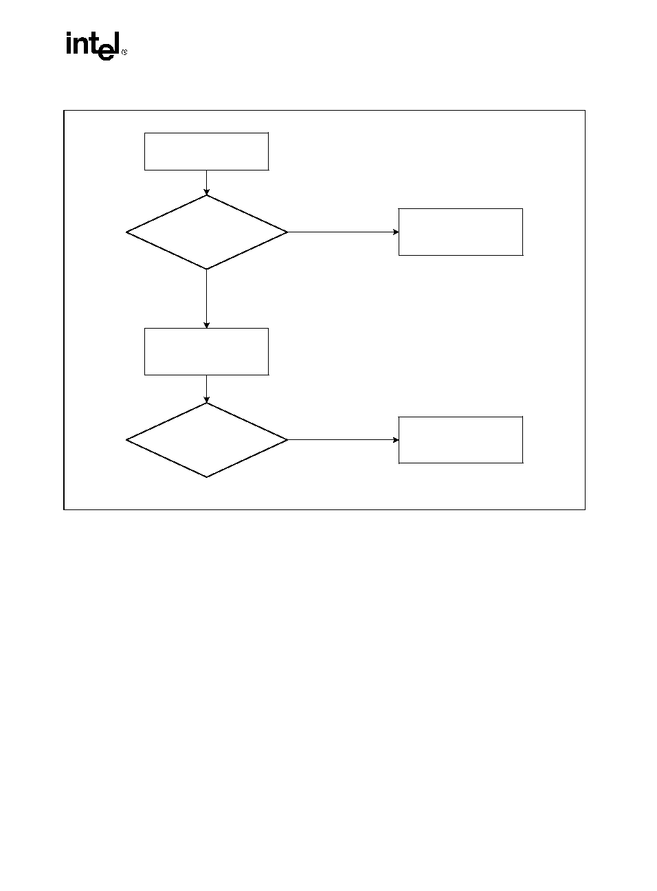
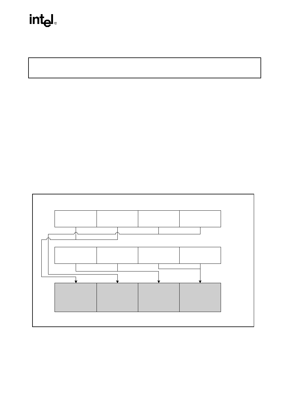
The Processor Brand String Method
Figure 2-4 describes the algorithm used for detection of the brand string. Processor brand identi-
fication software should execute this algorithm on all IA-32 architecture compatible processors.
This method (introduced with Pentium 4 processors) returns an ASCII brand identification
string and the maximum operating frequency of the processor to the EAX, EBX, ECX, and EDX
registers.
2-15
CPUID EXTENSIONS
How Brand Strings Work
To use the brand string method, execute CPUID with EAX input of 8000002H through
80000004H. For each input value, CPUID returns 16 ASCII characters using EAX, EBX, ECX,
and EDX. The returned string will be NULL terminated.
Table 2-7 shows the brand string that is returned by the first processor in the Pentium 4 processor
family.
Figure 2-4. Determination of Support for the Processor Brand String
OM15194
IF (EAX & 0x80000000)
CPUID
IF (EAX Return Value
>= 0x80000004)
CPUID
Function
Supported
True =>
Extended
EAX Return Value =
Max. Extended CPUID
Function Index
Input: EAX=1
Processor Brand
String Not
Supported
False
Processor Brand
String Supported
True

2-16
CPUID EXTENSIONS
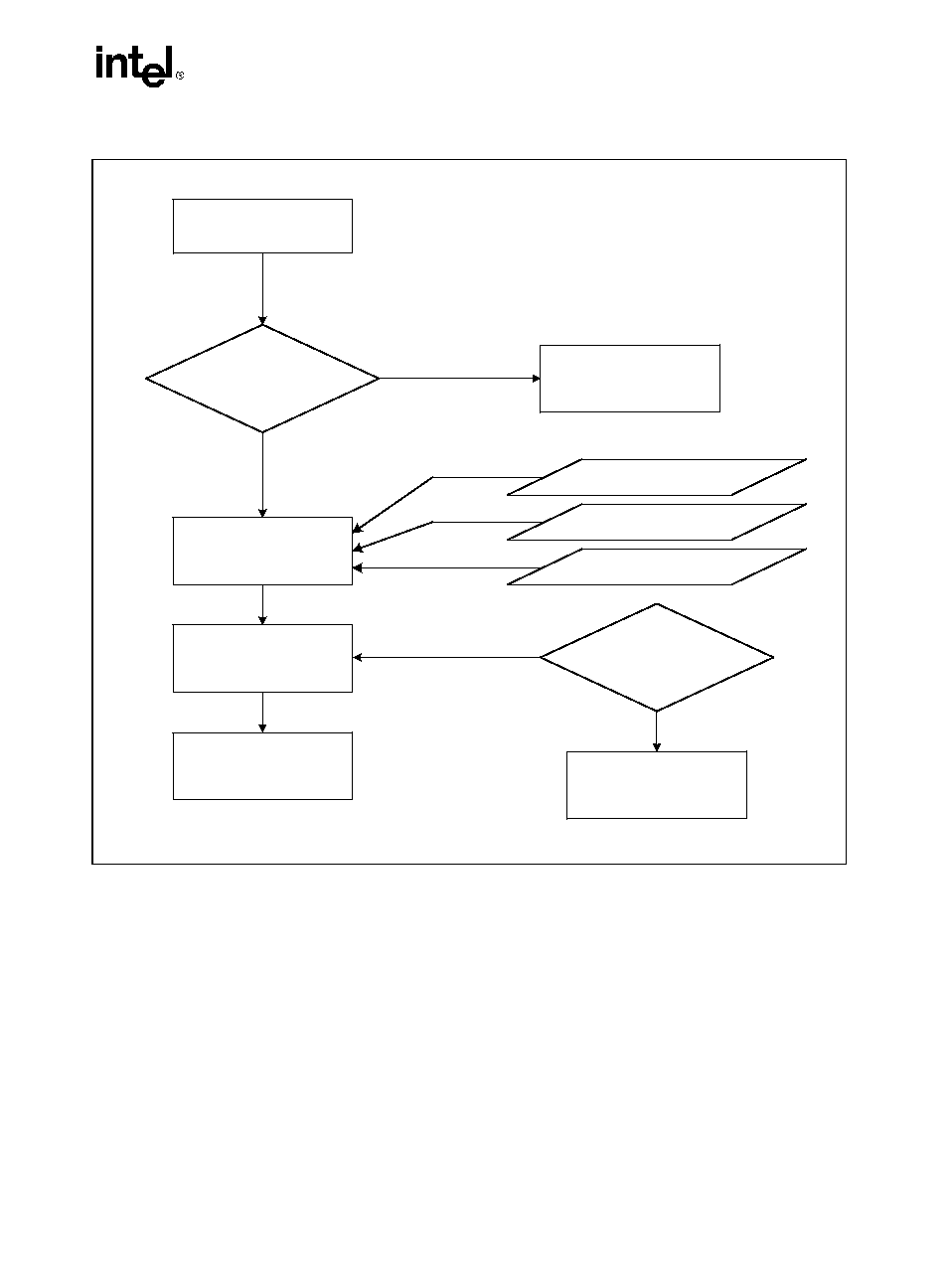
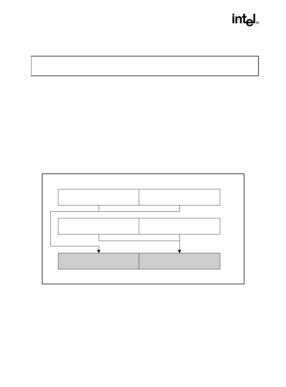
Extracting the Maximum Processor Frequency from Brand Strings
Figure 2-5 provides an algorithm which software can use to extract the maximum processor
operating frequency from the processor brand string.
NOTE
When a frequency is given in a brand string, it is the maximum qualified
frequency of the processor, not the frequency at which the processor is
currently running.
Table 2-7. Processor Brand String Returned with Pentium 4 Processor
EAX Input Value
Return Values
ASCII Equivalent
80000002H
EAX
= 20202020H
EBX
= 20202020H
ECX
= 20202020H
EDX
= 6E492020H
"
"
" "
" "
"nI "
80000003H
EAX
= 286C6574H
EBX
= 50202952H
ECX
= 69746E65H
EDX
= 52286D75H
"(let"
"P )R"
"itne"
"R(mu"
80000004H
EAX
= 20342029H
EBX
= 20555043H
ECX
= 30303531H
EDX
= 007A484DH
" 4 )"
" UPC"
"0051"
"\0zHM"
2-17
CPUID EXTENSIONS
The Processor Brand Index Method
The brand index method (introduced with Pentium III Xeon processors) provides an entry point
into a brand identification table that is maintained in memory by system software and is acces-
sible from system- and user-level code. In this table, each brand index is associate with an ASCII
brand identification string that identifies the official Intel family and model number of a
processor.
When CPUID executes with EAX set to 1, the processor returns a brand index to the low byte
in EBX. Software can then use this index to locate the brand identification string for the
processor in the brand identification table. The first entry (brand index 0) in this table is
Figure 2-5. Algorithm for Extracting Maximum Processor Frequency
OM15195
IF Substring Matched
"zHM", or
"zHG", or
"zHT"
Determine "Freq"
and "Multiplier"
True
Determine "Multiplier"
Scan "Brand String" in
Reverse Byte Order
Report Error
False
Scan Digits
Until Blank
Match
Substring
Determine "Freq"
Reverse Digits
To Decimal Value
Max. Qualified
Frequency =
"Freq" x "Multiplier"
"Freq" = XY.Z if
Digits = "Z.YX"
In Reverse Order
If "zHM"
If "zHG"
If "zHT"
Multiplier = 1 x 10
12
Multiplier = 1 x 10
9
Multiplier = 1 x 10
6

2-18
CPUID EXTENSIONS
reserved, allowing for backward compatibility with processors that do not support the brand
identification feature.
Table 2-8 shows brand indices that have identification strings associated with them.
Indicates versions of these processors that were introduced after the Pentium III processor
IA-32 Architecture Compatibility
CPUID is not supported in early models of the Intel486 processor or in any IA-32 processor
earlier than the Intel486 processor.
Operation
CASE (EAX) OF
EAX
= 0:
EAX
highest basic function input value understood by CPUID;
EBX
Vendor identification string;
EDX
Vendor identification string;
ECX
Vendor identification string;
Table 2-8. Mapping of Brand Indices and IA-32 Processor Brand Strings
Brand Index
Brand String
0H
This processor does not support the brand identification feature
01H
Intel
®
Celeron
®
processor
02H
Intel
®
Pentium
®
III processor
03H
Intel
®
Pentium
®
III Xeon
TM
processor; If processor signature = 000006B1h, then
"Intel
®
Celeron
®
processor"
04H
Intel
®
Pentium
®
III processor
06H
Mobile Intel
®
Pentium
®
III processor-M
07H
Mobile Intel
®
Celeron
®
processor
08H
Intel
®
Pentium
®
4 processor
09H
Intel
®
Pentium
®
4 processor
0AH
Intel
®
Celeron
®
processor
0BH
Intel
®
Xeon
TM
processor; If processor signature = 00000F13h, then "Intel
®
Xeon
TM
processor MP"
0CH
Intel
®
Xeon
TM
processor MP
0EH
Mobile Intel
®
Pentium
®
4 processor-M; If processor signature = 00000F13h, then
"Intel
®
Xeon
TM
processor"
0FH
Mobile Intel
®
Celeron
®
processor
13H
Mobile Intel
®
Celeron
®
processor
16H
Intel
®
Pentium
®
M processor
17H 0FFH
RESERVED
2-19
CPUID EXTENSIONS
BREAK;
EAX
= 1H:
EAX[3:0]
Stepping ID;
EAX[7:4]
Model;
EAX[11:8]
Family;
EAX[13:12]
Processor type;
EAX[15:14]
Reserved;
EAX[19:16]
Extended Model;
EAX[23:20]
Extended Family;
EAX[31:24]
Reserved;
EBX[7:0]
Brand Index;
EBX[15:8]
CLFLUSH Line Size;
EBX[16:23]
Reserved;
EBX[24:31]
Initial APIC ID;
ECX
Feature flags;
EDX
Feature flags;
BREAK;
EAX
= 2H:
EAX
Cache and TLB information;
EBX
Cache and TLB information;
ECX
Cache and TLB information;
EDX
Cache and TLB information;
BREAK;
EAX
= 3H:
EAX
Reserved;
EBX
Reserved;
ECX
ProcessorSerialNumber[31:0];
(* Pentium III processors only, otherwise reserved *)
EDX
ProcessorSerialNumber[63:32];
(* Pentium III processors only, otherwise reserved *
BREAK
EAX
= 4H:
EAX
Deterministic Cache Parameters Leaf; /* see page 2-2 */
EBX
Deterministic Cache Parameters Leaf;
ECX
Deterministic Cache Parameters Leaf;
EDX
Deterministic Cache Parameters Leaf;
BREAK;
EAX
= 5H:
EAX
EBX
MONITOR/MWAIT Leaf;
ECX
MONITOR/MWAIT Leaf;
EDX
MONITOR/MWAIT Leaf;
BREAK;
EAX
= 80000000H:
EAX
highest extended function input value understood by CPUID;
EBX
Reserved;
ECX
Reserved;
2-20
CPUID EXTENSIONS
EDX
Reserved;
BREAK;
EAX
= 80000001H:
EAX
Extended Processor Signature and Feature Bits (*Currently Reserved*);
EBX
Reserved;
ECX
Reserved;
EDX
Reserved;
BREAK;
EAX
= 80000002H:
EAX
Processor Brand String;
EBX
Processor Brand String, continued;
ECX
Processor Brand String, continued;
EDX
Processor Brand String, continued;
BREAK;
EAX
= 80000003H:
EAX
Processor Brand String, continued;
EBX
Processor Brand String, continued;
ECX
Processor Brand String, continued;
EDX
Processor Brand String, continued;
BREAK;
EAX
= 80000004H:
EAX
Processor Brand String, continued;
EBX
Processor Brand String, continued;
ECX
Processor Brand String, continued;
EDX
Processor Brand String, continued;
BREAK;
EAX
= 80000005H:
EAX
Reserved = 0;
EBX
Reserved = 0;
ECX
Reserved = 0;
EDX
Reserved = 0;
BREAK;
EAX
= 80000006H:
EAX
Reserved = 0;
EBX
Reserved = 0;
ECX
Cache information;
EDX
Reserved = 0;
BREAK;
EAX
= 80000007H:
EAX
Reserved = 0;
EBX
Reserved = 0;
ECX
Reserved = 0;
EDX
Reserved = 0;
BREAK;
EAX
= 80000008H:
EAX
Reserved = 0;
EBX
Reserved = 0;
2-21
CPUID EXTENSIONS
ECX
Reserved = 0;
EDX
Reserved = 0;
BREAK;
DEFAULT: (* EAX
> highest value recognized by CPUID *)
EAX
Reserved; (* undefined*)
EBX
Reserved; (* undefined*)
ECX
Reserved; (* undefined*)
EDX
Reserved; (* undefined*)
BREAK;
ESAC;
2-22
CPUID EXTENSIONS
3-1
CHAPTER 3
INSTRUCTION SET REFERENCE
3.1.
INTERPRETING THE INSTRUCTION REFERENCE PAGES
Prescott New Instructions use existing instruction formats. Instructions use the ModR/M format
and in general, operations are not duplicated to provide two directions (i.e., separate load and
store variants).
Besides opcodes, two kinds of notations describe information found in the ModR/M byte:
·
/digit: (digit between 0 and 7) indicates that the instruction uses only the r/m (register and memory)
operand. The reg field contains the digit that provides an extension to the instruction's opcode.
·
/digitR: (digit between 0 and 7) indicates that the instruction uses only the register operand (i.e.,
mod=11). The reg field contains the digit that provides an extension to the instruction's opcode.
·
/r: indicates that the ModR/M byte of an instruction contains both a register operand and an r/m
operand.
In addition, the following abbreviations are used:
r32
Intel architecture 32-bit integer register
xmm/m128
Indicates a 128-bit FP Streaming SIMD Extensions/Streaming SIMD Extensions
2 register or a 128-bit memory location.
xmm/m64
Indicates a 128-bit FP Streaming SIMD Extensions/Streaming SIMD Extensions
2 register or a 64-bit memory location.
xmm/m32
Indicates a 128-bit FP Streaming SIMD Extensions/Streaming SIMD Extensions
2 register or a 32-bit memory location.
mm/m64
Indicates a 64-bit integer register using MMXTM media enhancement technology
or a 64-bit memory location.
xmm/m128
Indicates a 128-bit integer register using MMX media enhancement technology or
a 128-bit memory location.
imm8
Indicates an immediate 8-bit operand.
ib
Indicates that an immediate byte operand follows the opcode, ModR/M byte or
scaled-indexing byte.
When there is ambiguity, xmm1 indicates the first source operand and xmm2 the second source
operand. For more information on notation, refer to the notation section in the IA-32 Intel
®
Architecture Software Developer's Manual, Volume 3.
3.2.
PRESCOTT NEW INSTRUCTIONS
This chapter describes the thirteen Precott New Instructions in detail. Appendix A summarizes
the new instructions.
3-2
INSTRUCTION SET REFERENCE
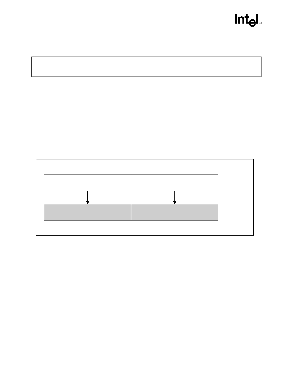
ADDSUBPD: Packed Double-FP Add/Subtract
Description
Adds the double-precision floating-point values in the high quadword of the source and desti-
nation operands and stores the result in the high quadword of the destination operand.
Subtracts the double-precision floating-point value in the low quadword of the source operand
from the low quadword of the destination operand and stores the result in the low quadword of
the destination operand.
Operation
xmm1[63-0] = xmm1[63-0] - xmm2/m128[63-0];
xmm1[127-64] = xmm1[127-64] + xmm2/m128[127-64];
Intel
®
C/C
++ Compiler Intrinsic Equivalent
ADDSUBPD
__m128d _mm_addsub_pd(__m128d a, __m128d b)
Opcode
Instruction
Description
66,0F,D0,/r
ADDSUBPD xmm1, xmm2/m128
Add/Subtract packed DP FP numbers from
xmm2/m128 to xmm1.
Figure 3-1. ADDSUBPD: Packed Double-FP Add/Subtract
OM15991
[127-64]
xmm1[127-64] + xmm2/m128[127-64]
xmm1[63-0] - xmm2/m128[63-0]
[63-0]
[127-64]
[63-0]
ADDSUBPD xmm1, xmm2/m128
RESULT:
xmm1
xmm2/m128
3-3
INSTRUCTION SET REFERENCE
ADDSUBPD: Packed Double-FP Add/Subtract (Continued)
Exceptions
When the source operand is a memory operand, it must be aligned on a 16-byte boundary or a
general-protection exception (#GP) will be generated.
Numeric Exceptions
Overflow, Underflow, Invalid, Precision, Denormal.
Protected Mode Exceptions
#GP(0)
For an illegal memory operand effective address in the CS, DS, ES, FS or
GS segments.
If memory operand is not aligned on a 16-byte boundary, regardless of
segment.
#SS(0)
For an illegal address in the SS segment.
#PF(fault-code)
For a page fault.
#NM
If TS bit in CR0 is set.
#XM
For an unmasked Streaming SIMD Extensions numeric exception
(CR4.OSXMMEXCPT = 1).
#UD
If CR0.EM = 1.
For an unmasked Streaming SIMD Extensions numeric exception
(CR4.OSXMMEXCPT = 0);
If CR4.OSFXSR(bit 9) = 0.
If CPUID.PNI(ECX bit 0) = 0.
Real Address Mode Exceptions
GP(0)
If any part of the operand would lie outside of the effective address space
from 0 to 0FFFFH.
If memory operand is not aligned on a 16-byte boundary, regardless of
segment.
#NM
If TS bit in CR0 is set.
#XM
For an unmasked Streaming SIMD Extensions numeric exception
(CR4.OSXMMEXCPT = 1).
#UD
If CR0.EM = 1.
For an unmasked Streaming SIMD Extensions numeric exception
(CR4.OSXMMEXCPT = 0).
3-4
INSTRUCTION SET REFERENCE
ADDSUBPD: Packed Double-FP Add/Subtract (Continued)
If CR4.OSFXSR(bit 9) = 0.
If CPUID.PNI(ECX bit 0) = 0.
Virtual 8086 Mode Exceptions
GP(0)
If any part of the operand would lie outside of the effective address space
from 0 to 0FFFFH.
If memory operand is not aligned on a 16-byte boundary, regardless of
segment.
#NM
If TS bit in CR0 is set.
#XM
For an unmasked Streaming SIMD Extensions numeric exception
(CR4.OSXMMEXCPT = 1).
#UD
If CR0.EM = 1.
For an unmasked Streaming SIMD Extensions numeric exception
(CR4.OSXMMEXCPT = 0).
If CR4.OSFXSR(bit 9) = 0.
If CPUID.PNI(ECX bit 0) = 0.
#PF(fault-code)
For a page fault.
3-5
INSTRUCTION SET REFERENCE
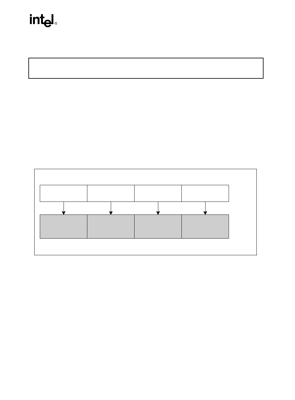
ADDSUBPS: Packed Single-FP Add/Subtract
Description
Adds odd-numbered single-precision floating-point values of the source operand with the corre-
sponding single-precision floating-point values from the destination operand; stores the result
in the odd-numbered values of the destination operand.
Subtracts the even-numbered single-precision floating-point values in the source operand from
the corresponding single-precision floating values in the destination operand; stores the result
into the even-numbered values of the destination operand.
Operation
xmm1[31-0] = xmm1[31-0] - xmm2/m128[31-0];
xmm1[63-32] = xmm1[63-32] + xmm2/m128[63-32];
xmm1[95-64] = xmm1[95-64] - xmm2/m128[95-64];
xmm1[127-96] = xmm1[127-96] + xmm2/m128[127-96];
Intel C/C
++ Compiler Intrinsic Equivalent
ADDSUBPS
__m128 _mm_addsub_ps(__m128 a, __m128 b)
Opcode
Instruction
Description
F2,0F,D0,/r
ADDSUBPS xmm1, xmm2/m128
Add/Subtract packed SP FP numbers from
xmm2/m128 to xmm1.
Figure 3-2. ADDSUBPS: Packed Single-FP Add/Subtract
OM15992
ADDSUBPS xmm1, xmm2/m128
RESULT:
xmm1
xmm2/
m128
xmm1[31-0] -
xmm2/m128[31-0]
[31-0]
xmm1[63-32] +
xmm2/m128[63-32]
[63-32]
xmm1[95-64] - xmm2/
m128[95-64]
[95-64]
xmm1[127-96] +
xmm2/m128[127-96]
[127-96]
[127-96]
[95-64]
[63-32]
[31-0]
3-6
INSTRUCTION SET REFERENCE
ADDSUBPS: Packed Single-FP Add/Subtract (Continued)
Exceptions
When the source operand is a memory operand, the operand must be aligned on a 16-byte
boundary or a general-protection exception (#GP) will be generated.
Numeric Exceptions
Overflow, Underflow, Invalid, Precision, Denormal.
Protected Mode Exceptions
#GP(0)
For an illegal memory operand effective address in the CS, DS, ES, FS or
GS segments.
If memory operand is not aligned on a 16-byte boundary, regardless of
segment.
#SS(0)
For an illegal address in the SS segment.
#PF(fault-code)
For a page fault.
#NM
If TS bit in CR0 is set.
#XM
For an unmasked Streaming SIMD Extensions numeric exception
(CR4.OSXMMEXCPT = 1).
#UD
If CR0.EM = 1.
For an unmasked Streaming SIMD Extensions numeric exception
(CR4.OSXMMEXCPT = 0).
If CR4.OSFXSR(bit 9) = 0.
If CPUID.PNI(ECX bit 0) = 0.
Real Address Mode Exceptions
GP(0)
If any part of the operand would lie outside of the effective address space
from 0 to 0FFFFH.
If memory operand is not aligned on a 16-byte boundary, regardless of
segment.
#NM
If TS bit in CR0 is set.
#XM
For an unmasked Streaming SIMD Extensions numeric exception
(CR4.OSXMMEXCPT = 1).
#UD
If CR0.EM = 1.
For an unmasked Streaming SIMD Extensions numeric exception
(CR4.OSXMMEXCPT = 0).
3-7
INSTRUCTION SET REFERENCE
ADDSUBPS: Packed Single-FP Add/Subtract (Continued)
If CR4.OSFXSR(bit 9) = 0.
If CPUID.PNI(ECX bit 0) = 0.
Virtual 8086 Mode Exceptions
GP(0)
If any part of the operand would lie outside of the effective address space
from 0 to 0FFFFH.
If memory operand is not aligned on a 16-byte boundary, regardless of
segment.
#NM
If TS bit in CR0 is set.
#XM
For an unmasked Streaming SIMD Extensions numeric exception
(CR4.OSXMMEXCPT = 1).
#UD
If CR0.EM = 1.
For an unmasked Streaming SIMD Extensions numeric exception
(CR4.OSXMMEXCPT = 0).
If CR4.OSFXSR(bit 9) = 0.
If CPUID.PNI(ECX bit 0) = 0.
#PF(fault-code)
For a page fault.

3-8
INSTRUCTION SET REFERENCE
FISTTP: Store Integer with Truncation
Description
FISTTP converts the value in ST into a signed integer using truncation (chop) as rounding mode,
transfers the result to the destination, and pop ST. FISTTP accepts word, short integer, and long
integer destinations.
The following table shows the results obtained when storing various classes of numbers in
integer format.
Notes:
F Means finite floating-point value.
Means integer.
Indicates floating-point invalid-operation (#IA) exception.
Operation
DEST
ST;
pop ST;
Flags Affected
C1 is cleared; C0, C2, C3 undefined.
Numeric Exceptions
Invalid, Stack Invalid (stack underflow), Precision.
Opcode
Instruction
Description
DF /1
DB /1
DD /1
FISTTP m16int
FISTTP m32int
FISTTP m64int
Store ST as a signed integer (truncate) in
m16int and pop ST.
Store ST as a signed integer (truncate) in
m32int and pop ST.
Store ST as a signed integer (truncate) in
m64int and pop ST.
ST(0)
DEST
- or Value Too Large for DEST Format
F
- 1
-
- 1 < F < +1
0
F
+1
+
+
or Value Too Large for DEST Format
NaN
3-9
INSTRUCTION SET REFERENCE
FISTTP: Store Integer with Truncation (Continued)
Protected Mode Exceptions
#GP(0)
If the destination is in a nonwritable segment.
For an illegal memory operand effective address in the CS, DS, ES, FS or
GS segments.
#SS(0)
For an illegal address in the SS segment.
#PF(fault-code)
For a page fault.
#AC(0)
If alignment checking is enabled and an unaligned memory reference is
made while the current privilege level is 3.
#NM
If CR0.EM = 1.
If TS bit in CR0 is set.
#UD
If CPUID.PNI(ECX bit 0) = 0.
Real Address Mode Exceptions
GP(0)
If any part of the operand would lie outside of the effective address space
from 0 to 0FFFFH.
#NM
If CR0.EM = 1.
If TS bit in CR0 is set.
#UD
If CPUID.PNI(ECX bit 0) = 0.
Virtual 8086 Mode Exceptions
GP(0)
If any part of the operand would lie outside of the effective address space
from 0 to 0FFFFH.
#NM
If CR0.EM = 1.
If TS bit in CR0 is set.
#UD
If CPUID.PNI(ECX bit 0) = 0.
#PF(fault-code)
For a page fault.
#AC(0)
For unaligned memory reference if the current privilege is 3.
3-10
INSTRUCTION SET REFERENCE
HADDPD: Packed Double-FP Horizontal Add
Description
Adds the double-precision floating-point values in the high and low quadwords of the destina-
tion operand and stores the result in the low quadword of the destination operand.
Adds the double-precision floating-point values in the high and low quadwords of the source
operand and stores the result in the high quadword of the destination operand.
Operation
xmm1[63-0] = xmm1[63-0] + xmm1[127-64];
xmm1[127-64] = xmm2/m128[63-0] + xmm2/m128[127-64];
Intel C/C
++ Compiler Intrinsic Equivalent
HADDPD __m128d _mm_hadd_pd(__m128d a, __m128d b)
Opcode
Instruction
Description
66,0F,7C,/r
HADDPD xmm1, xmm2/m128
Add horizontally packed DP FP numbers from
xmm2/m128 to xmm1.
Figure 3-3. HADDPD: Packed Double-FP Horizontal Add
OM15993
HADDPD xmm1, xmm2/m128
xmm1
xmm2
/m128
[63-0]
[127-64]
[127-64]
[63-0]
[63-0]
[127-64]
Result:
xmm1
xmm2/m128[63-0] +
xmm2/m128[127-64]
xmm1[63-0] + xmm1[127-64]
3-11
INSTRUCTION SET REFERENCE
HADDPD: Packed Double-FP Horizontal Add (Continued)
Exceptions
When the source operand is a memory operand, the operand must be aligned on a 16-byte
boundary or a general-protection exception (#GP) will be generated.
Numeric Exceptions
Overflow, Underflow, Invalid, Precision, Denormal.
Protected Mode Exceptions
#GP(0)
For an illegal memory operand effective address in the CS, DS, ES, FS or
GS segments.
If memory operand is not aligned on a 16-byte boundary, regardless of
segment.
#SS(0)
For an illegal address in the SS segment.
#PF(fault-code)
For a page fault.
#NM
If TS bit in CR0 is set.
#XM
For an unmasked Streaming SIMD Extensions numeric exception
(CR4.OSXMMEXCPT = 1).
#UD
If CR0.EM = 1.
For an unmasked Streaming SIMD Extensions numeric exception
(CR4.OSXMMEXCPT = 0);
If CR4.OSFXSR(bit 9) = 0.
If CPUID.PNI(ECX bit 0) = 0.
Real Address Mode Exceptions
GP(0)
If any part of the operand would lie outside of the effective address space
from 0 to 0FFFFH.
If memory operand is not aligned on a 16-byte boundary, regardless of
segment.
#NM
If TS bit in CR0 is set.
#XM
For an unmasked Streaming SIMD Extensions numeric exception
(CR4.OSXMMEXCPT = 1).
#UD
If CR0.EM = 1.
For an unmasked Streaming SIMD Extensions numeric exception
(CR4.OSXMMEXCPT = 0).
3-12
INSTRUCTION SET REFERENCE
HADDPD: Packed Double-FP Horizontal Add (Continued)
If CR4.OSFXSR(bit 9) = 0.
If CPUID.PNI(ECX bit 0) = 0.
Virtual 8086 Mode Exceptions
GP(0)
If any part of the operand would lie outside of the effective address space
from 0 to 0FFFFH.
If memory operand is not aligned on a 16-byte boundary, regardless of
segment.
#NM
If TS bit in CR0 is set.
#XM
For an unmasked Streaming SIMD Extensions numeric exception
(CR4.OSXMMEXCPT = 1).
#UD
If CR0.EM = 1.
For an unmasked Streaming SIMD Extensions numeric exception
(CR4.OSXMMEXCPT = 0).
If CR4.OSFXSR(bit 9) = 0.
If CPUID.PNI(ECX bit 0) = 0.
#PF(fault-code)
For a page fault.
3-13
INSTRUCTION SET REFERENCE
HADDPS: Packed Single-FP Horizontal Add
Description
Adds the single-precision floating-point values in the first and second dwords of the destination
operand and stores the result in the first dword of the destination operand.
Adds single-precision floating-point values in the third and fourth dword of the destination
operand and stores the result in the second dword of the destination operand.
Adds single-precision floating-point values in the first and second dword of the source operand
and stores the result in the third dword of the destination operand.
Adds single-precision floating-point values in the third and fourth dword of the source operand
and stores the result in the fourth dword of the destination operand.
Opcode
Instruction
Description
F2,0F,7C,/r
HADDPS xmm1, xmm2/m128
Add horizontally packed SP FP numbers from
xmm2/m128 to xmm1.
Figure 3-4. HADDPS: Packed Single-FP Horizontal Add
OM15994
HADDPS xmm1, xmm2/m128
RESULT:
xmm1
xmm2/
m128
x mm 1 [ 3 1 -0 ] +
x mm 1 [ 6 3 -3 2 ]
[31-0]
xm m1 [ 9 5 - 6 4 ] +
xm m1 [ 1 2 7 -9 6 ]
[63-32]
[63-32]
[31-0]
xmm1
[31-0]
[63-32]
x m m 2 / m 1 2 8
[ 3 1 -0 ] + xmm2 /
m1 2 8 [ 6 3 - 3 2 ]
[95-64]
x m m 2 / m 1 2 8
[ 9 5 -6 4 ] + xmm2 /
m 1 2 8 [ 1 2 7 - 9 6 ]
[127-96]
[127-96]
[95-64]
[95-64]
[127-96]
3-14
INSTRUCTION SET REFERENCE
HADDPS: Packed Single-FP Horizontal Add (Continued)
Operation
xmm1[31-0] = xmm1[31-0] + xmm1[63-32];
xmm1[63-32] = xmm1[95-64] + xmm1[127-96];
xmm1[95-64] = xmm2/m128[31-0] + xmm2/m128[63-32];
xmm1[127-96] = xmm2/m128[95-64] + xmm2/m128[127-96];
Intel C/C
++ Compiler Intrinsic Equivalent
HADDPS __m128 _mm_hadd_ps(__m128 a, __m128 b)
Exceptions
When the source operand is a memory operand, the operand must be aligned on a 16-byte
boundary or a general-protection exception (#GP) will be generated.
Numeric Exceptions
Overflow, Underflow, Invalid, Precision, Denormal.
Protected Mode Exceptions
#GP(0)
For an illegal memory operand effective address in the CS, DS, ES, FS or
GS segments.
If memory operand is not aligned on a 16-byte boundary, regardless of
segment.
#SS(0)
For an illegal address in the SS segment.
#PF(fault-code)
For a page fault.
#NM
If TS bit in CR0 is set.
#XM
For an unmasked Streaming SIMD Extensions numeric exception
(CR4.OSXMMEXCPT = 1).
#UD
If CR0.EM = 1.
For an unmasked Streaming SIMD Extensions numeric exception
(CR4.OSXMMEXCPT = 0).
If CR4.OSFXSR(bit 9) = 0.
If CPUID.PNI(ECX bit 0) = 0.
3-15
INSTRUCTION SET REFERENCE
HADDPS: Packed Single-FP Horizontal Add (Continued)
Real Address Mode Exceptions
GP(0)
If any part of the operand would lie outside of the effective address space
from 0 to 0FFFFH.
If memory operand is not aligned on a 16-byte boundary, regardless of
segment.
#NM
If TS bit in CR0 is set.
#XM
For an unmasked Streaming SIMD Extensions numeric exception
(CR4.OSXMMEXCPT = 1).
#UD
If CR0.EM = 1.
For an unmasked Streaming SIMD Extensions numeric exception
(CR4.OSXMMEXCPT = 0).
If CR4.OSFXSR(bit 9) = 0.
If CPUID.PNI(ECX bit 0) = 0.
Virtual 8086 Mode Exceptions
GP(0)
If any part of the operand would lie outside of the effective address space
from 0 to 0FFFFH.
If memory operand is not aligned on a 16-byte boundary, regardless of
segment.
#NM
If TS bit in CR0 is set.
#XM
For an unmasked Streaming SIMD Extensions numeric exception
(CR4.OSXMMEXCPT = 1).
#UD
If CR0.EM = 1.
For an unmasked Streaming SIMD Extensions numeric exception
(CR4.OSXMMEXCPT = 0).
If CR4.OSFXSR(bit 9) = 0.
If CPUID.PNI(ECX bit 0) = 0.
#PF(fault-code)
For a page fault.
3-16
INSTRUCTION SET REFERENCE
HSUBPD: Packed Double-FP Horizontal Subtract
Description
The HSUBPD instruction subtracts horizontally the packed DP FP numbers of both operands.
Subtracts the double-precision floating-point value in the high quadword of the destination
operand from the low quadword of the destination operand and stores the result in the low quad-
word of the destination operand.
Subtracts the double-precision floating-point value in the high quadword of the source operand
from the low quadword of the source operand and stores the result in the high quadword of the
destination operand.
Operation
xmm1[63-0] = xmm1[63-0] - xmm1[127-64];
xmm1[127-64] = xmm2/m128[63-0] - xmm2/m128[127-64];
Opcode
Instruction
Description
66,0F,7D,/r
HSUBPD xmm1, xmm2/m128
Subtract horizontally packed DP FP numbers
in xmm2/m128 from xmm1.
Figure 3-5. HSUBPD: Packed Double-FP Horizontal Subtract
OM15995
HSUBPD xmm1, xmm2/m128
xmm1
xmm2
/m128
[63-0]
[127-64]
[127-64]
[63-0]
[63-0]
[127-64]
Result:
xmm1
xmm2/m128[63-0] -
xmm2/m128[127-64]
xmm1[63-0] - xmm1[127-64]
3-17
INSTRUCTION SET REFERENCE
HSUBPD: Packed Double-FP Horizontal Subtract (Continued)
Intel C/C
++ Compiler Intrinsic Equivalent
HSUBPD __m128d _mm_hsub_pd(__m128d a, __m128d b)
Exceptions
When the source operand is a memory operand, the operand must be aligned on a 16-byte
boundary or a general-protection exception (#GP) will be generated.
Numeric Exceptions
Overflow, Underflow, Invalid, Precision, Denormal.
Protected Mode Exceptions
#GP(0)
For an illegal memory operand effective address in the CS, DS, ES, FS or
GS segments.
If memory operand is not aligned on a 16-byte boundary, regardless of
segment.
#SS(0)
For an illegal address in the SS segment.
#PF(fault-code)
For a page fault.
#NM
If TS bit in CR0 is set.
#XM
For an unmasked Streaming SIMD Extensions numeric exception
(CR4.OSXMMEXCPT = 1).
#UD
If CR0.EM = 1.
For an unmasked Streaming SIMD Extensions numeric exception
(CR4.OSXMMEXCPT = 0).
If CR4.OSFXSR(bit 9) = 0.
If CPUID.PNI(ECX bit 0) = 0.
3-18
INSTRUCTION SET REFERENCE
HSUBPD: Packed Double-FP Horizontal Subtract (Continued)
Real Address Mode Exceptions
GP(0)
If any part of the operand would lie outside of the effective address space
from 0 to 0FFFFH.
If memory operand is not aligned on a 16-byte boundary, regardless of
segment.
#NM
If TS bit in CR0 is set.
#XM
For an unmasked Streaming SIMD Extensions numeric exception
(CR4.OSXMMEXCPT = 1).
#UD
If CR0.EM = 1.
For an unmasked Streaming SIMD Extensions numeric exception
(CR4.OSXMMEXCPT = 0).
If CR4.OSFXSR(bit 9) = 0.
If CPUID.PNI(ECX bit 0) = 0.
Virtual 8086 Mode Exceptions
GP(0)
If any part of the operand would lie outside of the effective address space
from 0 to 0FFFFH.
If memory operand is not aligned on a 16-byte boundary, regardless of
segment.
#NM
If TS bit in CR0 is set.
#XM
For an unmasked Streaming SIMD Extensions numeric exception
(CR4.OSXMMEXCPT = 1).
#UD
If CR0.EM = 1.
For an unmasked Streaming SIMD Extensions numeric exception
(CR4.OSXMMEXCPT = 0).
If CR4.OSFXSR(bit 9) = 0.
If CPUID.PNI(ECX bit 0) = 0.
#PF(fault-code)
For a page fault.

3-19
INSTRUCTION SET REFERENCE
HSUBPS: Packed Single-FP Horizontal Subtract
Description
Subtracts the single-precision floating-point value in the second dword of the destination
operand from the first dword of the destination operand and stores the result in the first dword
of the destination operand.
Subtracts the single-precision floating-point value in the fourth dword of the destination operand
from the third dword of the destination operand and stores the result in the second dword of the
destination operand.
Subtracts the single-precision floating-point value in the second dword of the source operand
from the first dword of the source operand and stores the result in the third dword of the desti-
nation operand.
Subtracts the single-precision floating-point value in the fourth dword of the source operand
from the third dword of the source operand and stores the result in the fourth dword of the desti-
nation operand.
Opcode
Instruction
Description
F2,0F,7D,/r
HSUBPS xmm1, xmm2/m128
Subtract horizontally packed SP FP numbers
in xmm2/m128 from xmm1.
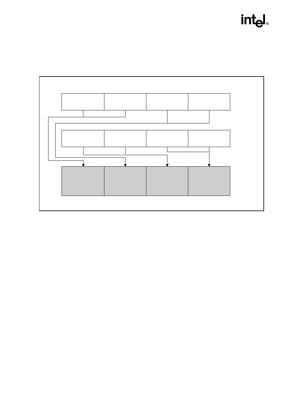
3-20
INSTRUCTION SET REFERENCE
HSUBPS: Packed Single-FP Horizontal Subtract (Continued)
Operation
xmm1[31-0] = xmm1[31-0] - xmm1[63-32];
xmm1[63-32] = xmm1[95-64] - xmm1[127-96];
xmm1[95-64] = xmm2/m128[31-0] - xmm2/m128[63-32];
xmm1[127-96] = xmm2/m128[95-64] - xmm2/m128[127-96];
Intel C/C
++ Compiler Intrinsic Equivalent
HSUBPS __m128 _mm_hsub_ps(__m128 a, __m128 b)
Exceptions
When the source operand is a memory operand, the operand must be aligned on a 16-byte
boundary or a general-protection exception (#GP) will be generated.
Numeric Exceptions
Overflow, Underflow, Invalid, Precision, Denormal.
Figure 3-6. HSUBPS: Packed Single-FP Horizontal Subtract
OM15996
HSUBPS xmm1, xmm2/m128
RESULT:
xmm1
xmm2/
m128
xmm1 [ 3 1 -0 ] -
xm m1 [ 6 3 - 3 2 ]
[31-0]
xmm1 [ 9 5 -6 4 ] -
xm m1 [ 1 2 7 -9 6 ]
[63-32]
[63-32]
[31-0]
xmm1
[31-0]
[63-32]
x m m 2 / m 1 2 8
[ 31 -0 ] - xmm2 /
m 1 2 8 [ 6 3 -3 2 ]
[95-64]
x m m 2 / m 1 2 8
[9 5-64 ] - xmm2 /
m1 2 8 [ 1 2 7 -9 6 ]
[127-96]
[127-96]
[95-64]
[95-64]
[127-96]
3-21
INSTRUCTION SET REFERENCE
HSUBPS: Packed Single-FP Horizontal Subtract (Continued)
Protected Mode Exceptions
#GP(0)
For an illegal memory operand effective address in the CS, DS, ES, FS or
GS segments.
If memory operand is not aligned on a 16-byte boundary, regardless of
segment.
#SS(0)
For an illegal address in the SS segment.
#PF(fault-code)
For a page fault.
#NM
If TS bit in CR0 is set.
#XM
For an unmasked Streaming SIMD Extensions numeric exception
(CR4.OSXMMEXCPT = 1).
#UD
If CR0.EM = 1.
For an unmasked Streaming SIMD Extensions numeric exception
(CR4.OSXMMEXCPT = 0).
If CR4.OSFXSR(bit 9) = 0.
If CPUID.PNI(ECX bit 0) = 0.
Real Address Mode Exceptions
GP(0)
If any part of the operand would lie outside of the effective address space
from 0 to 0FFFFH.
If memory operand is not aligned on a 16-byte boundary, regardless of
segment.
#NM
If TS bit in CR0 is set.
#XM
For an unmasked Streaming SIMD Extensions numeric exception
(CR4.OSXMMEXCPT = 1).
#UD
If CR0.EM = 1.
For an unmasked Streaming SIMD Extensions numeric exception
(CR4.OSXMMEXCPT = 0).
If CR4.OSFXSR(bit 9) = 0.
If CPUID.PNI(ECX bit 0) = 0.
3-22
INSTRUCTION SET REFERENCE
HSUBPS: Packed Single-FP Horizontal Subtract (Continued)
Virtual 8086 Mode Exceptions
GP(0)
If any part of the operand would lie outside of the effective address space
from 0 to 0FFFFH.
If memory operand is not aligned on a 16-byte boundary, regardless of
segment.
#NM
If TS bit in CR0 is set.
#XM
For an unmasked Streaming SIMD Extensions numeric exception
(CR4.OSXMMEXCPT = 1).
#UD
If CR0.EM = 1.
For an unmasked Streaming SIMD Extensions numeric exception
(CR4.OSXMMEXCPT = 0).
If CR4.OSFXSR(bit 9) = 0.
If CPUID.PNI(ECX bit 0) = 0.
#PF(fault-code)
For a page fault.
3-23
INSTRUCTION SET REFERENCE
LDDQU: Load Unaligned Integer 128 bits
Description
The instruction is functionally similar to MOVDQU xmm, m128 for loading from memory. That
is: 16 bytes of data starting at an address specified by the source memory operand (second
operand) are fetched from memory and placed in a destination register (first operand). The
source operand need not be aligned on a 16-byte boundary. Up to 32 bytes may be loaded from
memory; this is implementation dependent.
This instruction may improve performance relative to MOVDQU if the source operand crosses
a cache line boundary. In situations that require the data loaded by LDDQU be modified and
stored to the same location, use MOVDQU or MOVDQA instead of LDDQU. To move a double
quadword to or from memory locations that are known to be aligned on 16-byte boundaries, use
the MOVDQA instruction.
Implementation Notes
·
If the source is aligned to a 16-byte boundary, based on the implementation, the 16 bytes
may be loaded more than once. For that reason, the usage of LDDQU should be avoided
when using uncached or write-combining (WC) memory regions. For uncached or WC
memory regions, keep using MOVDQU.
·
This instruction is a replacement for MOVDQU (load) in situations where cache line splits
significantly affect performance. It should not be used in situations where store-load
forwarding is performance critical. If performance of store-load forwarding is critical to
the application, use MOVDQA store-load pairs when data is 128-bit aligned or MOVDQU
store-load pairs when data is 128-bit unaligned.
Operation
xmm[127-0] = m128;
Intel C/C
++ Compiler Intrinsic Equivalent
HADDPS __m128i _mm_lddqu_si128(__m128i const *p)
Numeric Exceptions
None
Opcode
Instruction
Description
F2,0F,F0,/r
LDDQU xmm, mem
Load data from mem and return 128 bits in
an xmm register.
3-24
INSTRUCTION SET REFERENCE
LDDQU: Load Unaligned Integer 128 bits (Continued)
Protected Mode Exceptions
#GP(0)
For an illegal memory operand effective address in the CS, DS, ES, FS or
GS segments.
#SS(0)
For an illegal address in the SS segment.
#PF(fault-code)
For a page fault.
#NM
If TS bit in CR0 is set.
#UD
If CR4.OSFXSR(bit 9) = 0.
If CR0.EM = 1.
If CPUID.PNI(ECX bit 0) = 0.
#AC(0)
If alignment checking is enabled and an unaligned memory reference is
made while the current privilege level is 3.
Real Address Mode Exceptions
GP(0)
If any part of the operand would lie outside of the effective address space
from 0 to 0FFFFH.
#NM
If TS bit in CR0 is set.
#UD
If CR0.EM = 1.
If CR4.OSFXSR(bit 9) = 0.
If CPUID.PNI(ECX bit 0) = 0.
Virtual 8086 Mode Exceptions
GP(0)
If any part of the operand would lie outside of the effective address space
from 0 to 0FFFFH.
#NM
If TS bit in CR0 is set.
#UD
If CR0.EM = 1.
If CR4.OSFXSR(bit 9) = 0.
If CPUID.PNI(ECX bit 0) = 0.
#PF(fault-code)
For a page fault.
#AC(0)
If alignment checking is enabled and an unaligned memory reference is
made.

3-25
INSTRUCTION SET REFERENCE
MONITOR: Setup Monitor Address
Description
The MONITOR instruction arms the address monitoring hardware using the address specified
in EAX. The address range that the monitoring hardware will check for store operations can be
determined by the CPUID instruction. The monitoring hardware will detect stores to an address
within the address range and triggers the monitor hardware when the write is detected. The state
of the monitor hardware is used by the MWAIT instruction.
The content of EAX is an effective address. By default, the DS segment is used to create a linear
address that is then monitored. Segment overrides can be used with the MONITOR instruction.
ECX and EDX are used to communicate other information to the MONITOR instruction. ECX
specifies optional extensions for the MONITOR instruction. EDX specifies optional hints for
the MONITOR instruction and does not change the architectural behavior of the instruction. For
Prescott processor, no extensions or hints are defined. Specifying undefined hints in EDX are
ignored by the processor, whereas specifying undefined extensions in ECX will raise a general
protection fault exception on the execution of the MONITOR instruction.
The address range must be in memory of write-back type. Only write-back memory type stores
to the monitored address range will trigger the monitoring hardware. If the address range is not
in memory of write-back type, the address monitor hardware may not be armed properly. The
MONITOR instruction is ordered as a load operation with respect to other memory transactions.
The MONITOR instruction can be used at all privilege levels and is subject to all permission
checking and faults associated with a byte load. Like a load, the MONITOR instruction sets the
A-bit but not the D-bit in the page tables. The MONITOR CPUID feature flag (bit 3 of ECX
when CPUID is executed with EAX=1) indicates the availability of MONITOR and MWAIT
instructions in the processor. When set, the unconditional execution of MONITOR is supported
at privilege levels 0 and conditional execution at privilege levels 1 through 3 (software should
test for the appropriate support of these instructions before unconditional use). The operating
system or system BIOS may disable this instruction through the IA32_MISC_ENABLES MSR;
disabling the instruction clears the CPUID feature flag and causes execution of the MONITOR
instruction to generate an illegal opcode exception.
Opcode
Instruction
Description
0F,01,C8
MONITOR
Sets up a linear address range to be monitored by
hardware and activates the monitor. The address
range should be of a write-back memory caching
type.
3-26
INSTRUCTION SET REFERENCE
MONITOR: Setup Monitor Address (Continued)
Operation
MONITOR sets up an address range for the monitor hardware using the content of EAX as an
effective address and puts the monitor hardware in armed state. The memory address range
should be within memory of the write-back caching type. A store to the specified address range
will trigger the monitor hardware. The content of ECX and EDX are used to communicate other
information to the monitor hardware.
Intel C/C
++ Compiler Intrinsic Equivalent
MONITOR void _mm_monitor(void const *p, unsigned extensions,unsigned
hints)
Exceptions
None
Protected Mode Exceptions
#GP(0)
For an illegal memory operand effective address in the CS, DS, ES, FS or
GS segments.
#GP(0)
For ECX has a value other than 0.
#SS(0)
For an illegal address in the SS segment.
#PF(fault-code)
For a page fault (TBD).
#UD
If CPUID feature flag MONITOR is 0.
If executed at privilege level 1 through 3 when the instruction is not avail-
able.
If LOCK, REP, REPNE/NZ and Operand Size override prefixes are used.
Real Address Mode Exceptions
#GP
If any part of the operand lies outside of the effective address space from
0 to FFFFH.
#GP(0)
For ECX has a value other than 0.
#UD
If CPUID feature flag MONITOR is 0.
If LOCK, REP, REPNE/NZ and Operand Size override prefixes are used.
3-27
INSTRUCTION SET REFERENCE
MONITOR: Setup Monitor Address (Continued)
Virtual 8086 Mode Exceptions
#GP
If any part of the operand lies outside of the effective address space from
0 to FFFFH.
#GP(0)
For ECX has a value other than 0.
#UD
If CPUID feature flag MONITOR is 0.
If executed at privilege level 1 through 3 when the instruction is not avail-
able.
If LOCK, REP, REPNE/NZ and Operand Size override prefixes are used.
#PF(fault-code)
For a page fault.
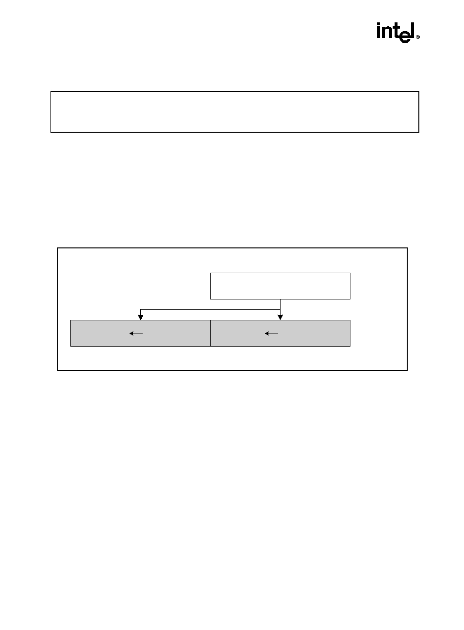
3-28
INSTRUCTION SET REFERENCE
MOVDDUP: Move One Double-FP and Duplicate
Description
The linear address corresponds to the address of the least-significant byte of the referenced
memory data. When a memory address is indicated, the 8 bytes of data at memory location m64
are loaded. When the register-register form of this operation is used, the lower half of the 128-
bit source register is duplicated and copied into the 128-bit destination register.
Operation
if (source == m64) {
// load instruction
xmm1[63-0] = m64;
xmm1[127-64] = m64;
}
else {
// move instruction
xmm1[63-0] = xmm2[63-0];
xmm1[127-64] = xmm2[63-0];
}
Opcode
Instruction
Description
F2,0F,12,/r
MOVDDUP xmm1, xmm2/m64
Move 64 bits representing the lower DP
data element from xmm2/m64 to xmm1
register and duplicate.
Figure 3-7. MOVDDUP: Move One Double-FP and Duplicate
OM15997
xmm1[127-64] xmm2/m64[63-0]
xmm1[63-0] xmm2/m64[63-0]
[63-0]
[127-64]
[63-0]
MOVDDUP xmm1, xmm2/m64
RESULT:
xmm1
xmm2/m64
3-29
INSTRUCTION SET REFERENCE
MOVDDUP: Move One Double-FP and Duplicate (Continued)
Intel C/C
++ Compiler Intrinsic Equivalent
MOVDDUP
__m128d _mm_movedup_pd(__m128d a)
__m128d _mm_loaddup_pd(double const * dp)
Exceptions
None
Numeric Exceptions
None
Protected Mode Exceptions
#GP(0)
For an illegal memory operand effective address in the CS, DS, ES, FS or
GS segments.
#SS(0)
For an illegal address in the SS segment.
#PF(fault-code)
For a page fault.
#NM
If TS bit in CR0 is set.
#UD
If CR0.EM = 1.
If CR4.OSFXSR(bit 9) = 0.
If CPUID.PNI(ECX bit 0) = 0.
#AC(0)
If alignment checking is enabled and an unaligned memory reference is
made while the current privilege level is 3.
Real Address Mode Exceptions
GP(0)
If any part of the operand would lie outside of the effective address space
from 0 to 0FFFFH.
#NM
If TS bit in CR0 is set.
#UD
If CR0.EM = 1.
If CR4.OSFXSR(bit 9) = 0.
If CPUID.PNI(ECX bit 0) = 0.
3-30
INSTRUCTION SET REFERENCE
MOVDDUP: Move One Double-FP and Duplicate (Continued)
Virtual 8086 Mode Exceptions
GP(0)
If any part of the operand would lie outside of the effective address space
from 0 to 0FFFFH.
#NM
If TS bit in CR0 is set.
#UD
If CR0.EM = 1.
If CR4.OSFXSR(bit 9) = 0.
If CPUID.PNI(ECX bit 0) = 0.
#PF(fault-code)
For a page fault.
#AC(0)
If alignment checking is enabled and an unaligned memory reference is
made.
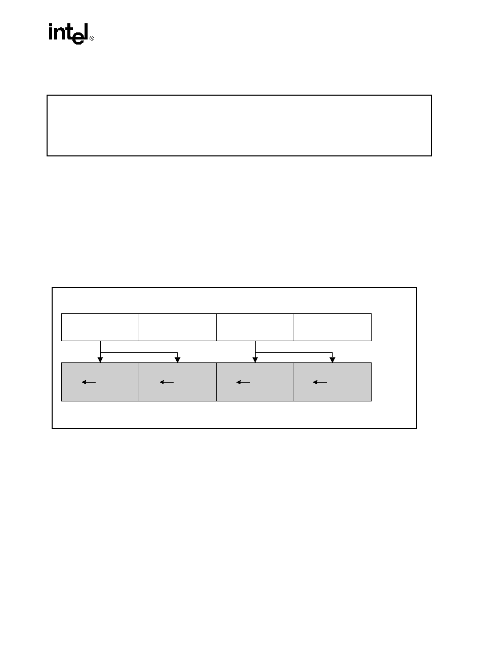
3-31
INSTRUCTION SET REFERENCE
MOVSHDUP: Move Packed Single-FP High and Duplicate
Description
The linear address corresponds to the address of the least-significant byte of the referenced
memory data. When a memory address is indicated, the 16 bytes of data at memory location
m128 are loaded and the single-precision elements in positions 1 and 3 are duplicated. When the
register-register form of this operation is used, the same operation is performed but with data
coming from the 128-bit source register.
Opcode
Instruction
Description
F3,0F,16,/r
MOVSHDUP xmm1, xmm2/m128
Move two single-precision floating-point
values from the higher 32-bit operand of
each qword in xmm2/m128 to xmm1 and
duplicate each 32-bit operand to the lower
32-bits of each qword.
Figure 3-8. MOVSHDUP: Move Packed Single-FP High and Duplicate
OM15998
MOVSHDUP xmm1, xmm2/m128
RESULT:
xmm1
xmm2/
m128
xm m1 [ 3 1 - 0 ]
xmm2/
m1 2 8 [ 6 3 - 3 2 ]
[31-0]
xm m1 [ 6 3 - 3 2 ]
xmm2/
m 1 2 8 [ 6 3 -3 2 ]
[63-32]
x mm 1 [ 9 5 -6 4 ]
xmm2/
m1 2 8 [ 1 2 7 -9 6 ]
[95-64]
xm m1 [ 1 2 7 -9 6 ]
xmm2/
m 1 2 8 [ 1 2 7 - 9 6 ]
[127-96]
[127-96]
[95-64]
[63-32]
[31-0]
3-32
INSTRUCTION SET REFERENCE
MOVSHDUP: Move Packed Single-FP High and Duplicate
(Continued)
Operation
if (source == m128) {
// load instruction
xmm1[31-0] = m128[63-32];
xmm1[63-32] = m128[63-32]
xmm1[95-64] = m128[127-96];
xmm1[127-96] = m128[127-96];
}
else {
// move instruction
xmm1[31-0] = xmm2[63-32];
xmm1[63-32] = xmm2[63-32];
xmm1[95-64] = xmm2[127-96];
xmm1[127-96] = xmm2[127-96];
}
Intel C/C
++ Compiler Intrinsic Equivalent
MOVSHDUP __m128 _mm_movehdup_ps(__m128 a)
Exceptions
General protection exception if not aligned on 16-byte boundary, regardless of segment.
Numeric Exceptions
None
Protected Mode Exceptions
#GP(0)
For an illegal memory operand effective address in the CS, DS, ES, FS or
GS segments.
#SS(0)
For an illegal address in the SS segment.
#PF(fault-code)
For a page fault.
#NM
If TS bit in CR0 is set.
#UD
If CR0.EM = 1.
If CR4.OSFXSR(bit 9) = 0.
If CPUID.PNI(ECX bit 0) = 0.
3-33
INSTRUCTION SET REFERENCE
MOVSHDUP: Move Packed Single-FP High and Duplicate
(Continued)
Real Address Mode Exceptions
GP(0)
If any part of the operand would lie outside of the effective address space
from 0 to 0FFFFH.
#NM
If TS bit in CR0 is set.
#UD
If CR0.EM = 1.
If CR4.OSFXSR(bit 9) = 0.
If CPUID.PNI(ECX bit 0) = 0.
Virtual 8086 Mode Exceptions
GP(0)
If any part of the operand would lie outside of the effective address space
from 0 to 0FFFFH.
#NM
If TS bit in CR0 is set.
#UD
If CR0.EM = 1.
If CR4.OSFXSR(bit 9) = 0.
If CPUID.PNI(ECX bit 0) = 0.
#PF(fault-code)
For a page fault.
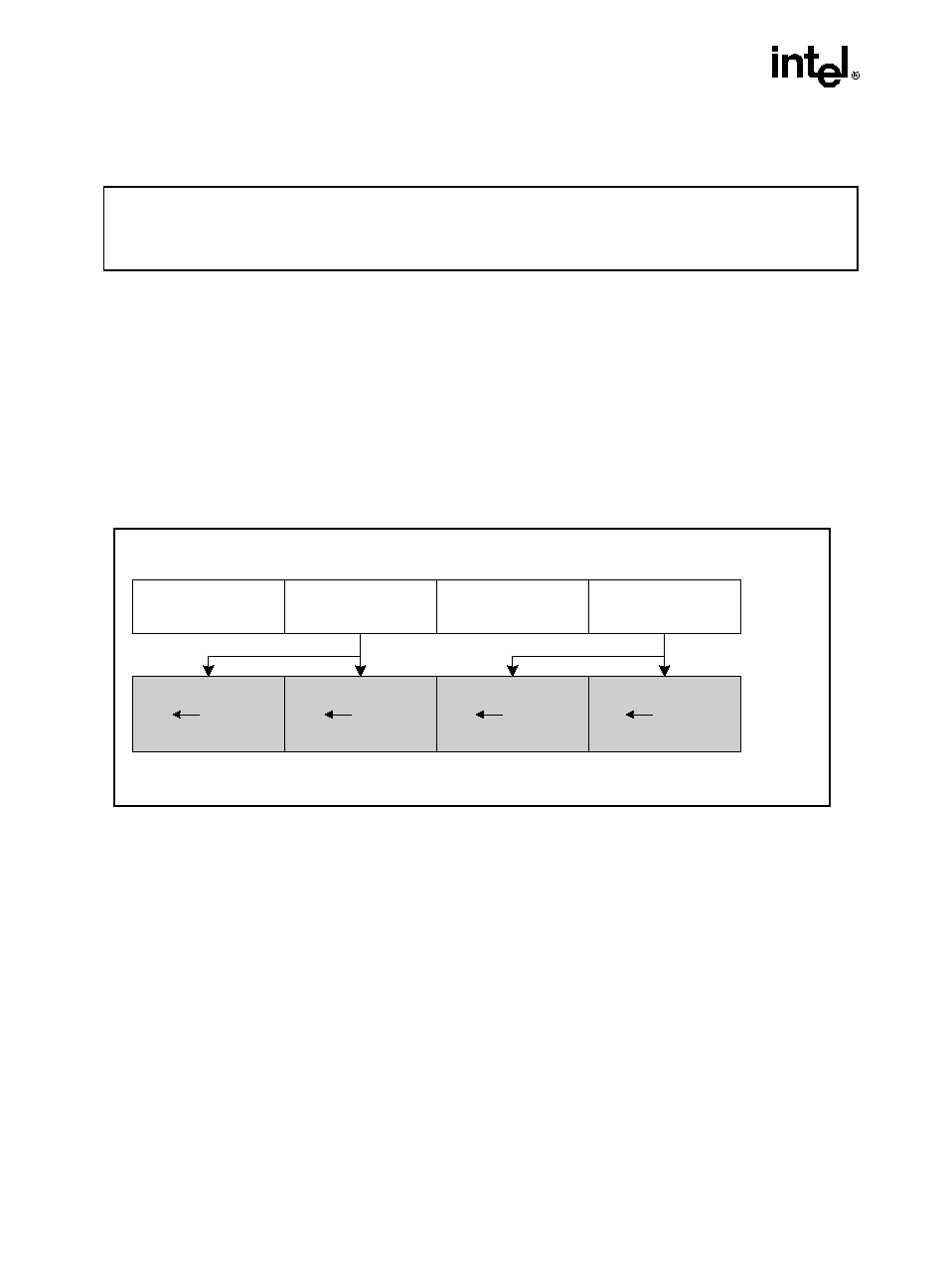
3-34
INSTRUCTION SET REFERENCE
MOVSLDUP: Move Packed Single-FP Low and Duplicate
Description
The linear address corresponds to the address of the least-significant byte of the referenced
memory data. When a memory address is indicated, the 16 bytes of data at memory location
m128 are loaded and the single-precision elements in positions 0 and 2 are duplicated. When the
register-register form of this operation is used, the same operation is performed but with data
coming from the 128-bit source register.
Operation
if (source == m128) {
// load instruction
xmm1[31-0] = m128[31-0];
xmm1[63-32] = m128[31-0]
xmm1[95-64] = m128[95-64];
xmm1[127-96] = m128[95-64];
}
else {
// move instruction
Opcode
Instruction
Description
F3,0F,12,/r
MOVSLDUP xmm1, xmm2/m128
Move 128 bits representing packed SP
data elements from xmm2/m128 to xmm1
register and duplicate low.
Figure 3-9. MOVSLDUP: Move Packed Single-FP Low and Duplicate
OM15999
MOVSLDUP xmm1, xmm2/m128
RESULT:
xmm1
xmm2/
m128
xm m1 [ 3 1 - 0 ]
xmm2/
m 1 2 8 [ 3 1 -0 ]
[31-0]
xm m1 [ 6 3 - 3 2 ]
xmm2/
m1 2 8 [ 3 1 - 0 ]
[63-32]
x mm 1 [ 9 5 -6 4 ]
xmm2/
m1 2 8 [ 9 5 - 6 4 ]
[95-64]
xm m1 [ 1 2 7 -9 6 ]
xmm2/
m 1 2 8 [ 9 5 -6 4 ]
[127-96]
[127-96]
[95-64]
[63-32]
[31-0]
3-35
INSTRUCTION SET REFERENCE
MOVSLDUP: Move Packed Single-FP Low and Duplicate
(Continued)
xmm1[31-0] = xmm2[31-0];
xmm1[63-32] = xmm2[31-0];
xmm1[95-64] = xmm2[95-64];
xmm1[127-96] = xmm2[95-64];
}
Intel C/C
++ Compiler Intrinsic Equivalent
MOVSLDUP__m128 _mm_moveldup_ps(__m128 a)
Exceptions
General protection exception if not aligned on 16-byte boundary, regardless of segment.
Numeric Exceptions
None
Protected Mode Exceptions
#GP(0)
For an illegal memory operand effective address in the CS, DS, ES, FS or
GS segments.
#SS(0)
For an illegal address in the SS segment.
#PF(fault-code)
For a page fault.
#NM
If TS bit in CR0 is set.
#UD
If CR0.EM = 1.
If CR4.OSFXSR(bit 9) = 0.
If CPUID.PNI(ECX bit 0) = 0.
Real Address Mode Exceptions
GP(0)
If any part of the operand would lie outside of the effective address space
from 0 to 0FFFFH.
#NM
If TS bit in CR0 is set.
#UD
If CR0.EM = 1.
If CR4.OSFXSR(bit 9) = 0.
If CPUID.PNI(ECX bit 0) = 0.
3-36
INSTRUCTION SET REFERENCE
MOVSLDUP: Move Packed Single-FP Low and Duplicate
(Continued)
Virtual 8086 Mode Exceptions
GP(0)
If any part of the operand would lie outside of the effective address space
from 0 to 0FFFFH.
#NM
If TS bit in CR0 is set.
#UD
If CR0.EM = 1.
If CR4.OSFXSR(bit 9) = 0.
If CPUID.PNI(ECX bit 0) = 0.
#PF(fault-code)
For a page fault.
3-37
INSTRUCTION SET REFERENCE
MWAIT: Monitor Wait
Description
The MWAIT instruction is designed to operate with the MONITOR instruction. The two instruc-
tions allow the definition of an address at which to `wait' (MONITOR) and an instruction that
causes a predefined `implementation-dependent-optimized operation' to commence at the
`wait' address (MWAIT). The execution of MWAIT is a hint to the processor that it can enter an
implementation-dependent-optimized state while waiting for an event or a store operation to the
address range armed by the preceding MONITOR instruction in program flow.
EAX and ECX is used to communicate other information to the MWAIT instruction, such as the
kind of optimized state the processor should enter. ECX specifies optional extensions for the
MWAIT instruction. EAX may contain hints such as the preferred optimized state the processor
should enter. For Pentium 4 processors with CPUID signature family = 15 and model = 3, all
non-zero values for EAX and ECX are reserved. The processor will raise a general protection
fault on the execution of MWAIT instruction with reserved values in ECX, whereas it ignores
the setting of reserved bits in EAX.
A store to the address range armed by the MONITOR instruction, an interrupt, an NMI or SMI,
a debug exception, a machine check exception, the BINIT# signal, the INIT# signal, or the
RESET# signal will exit the implementation-dependent-optimized state. Note that an interrupt
will cause the processor to exit only if the state was entered with interrupts enabled.
If a store to the address range causes the processor to exit, execution will resume at the instruc-
tion following the MWAIT instruction. If an interrupt (including NMI) caused the processor to
exit the implementation-dependent-optimized state, the processor will exit the state and handle
the interrupt. If an SMI caused the processor to exit the implementation-dependent-optimized
state, execution will resume at the instruction following MWAIT after handling of the SMI.
Unlike the HLT instruction, the MWAIT instruction does not support a restart at the MWAIT
instruction. There may also be other implementation-dependent events or time-outs that may
take the processor out of the implementation-dependent-optimized state and resume execution
at the instruction following the MWAIT.
If the preceding MONITOR instruction did not successfully arm an address range or if the
MONITOR instruction has not been executed prior to executing MWAIT, then the processor will
not enter the implementation-dependent-optimized state. Execution will resume at the instruc-
tion following the MWAIT.
Opcode
Instruction
Description
0F,01,C9
MWAIT
A hint that allows the processor to stop instruction
execution and enter an implementation-dependent
optimized state until occurrence of a class of events; it is
architecturally identical to a NOP instruction.
3-38
INSTRUCTION SET REFERENCE
MWAIT: Monitor Wait (Continued)
The MWAIT instruction can be executed at any privilege level. The MONITOR CPUID feature
flag (ECX[bit 3] when CPUID is executed with EAX = 1) indicates the availability of the
MONITOR and MWAIT instruction in a processor. When set, the unconditional execution of
MWAIT is supported at privilege levels 0 and conditional execution is supported at privilege
levels 1 through 3 (software should test for the appropriate support of these instructions before
unconditional use).
The operating system or system BIOS may disable this instruction using the
IA32_MISC_ENABLES MSR; disabling the instruction clears the CPUID feature flag and
causes execution of the MWAIT instruction to generate an illegal opcode exception.
Operation
// MWAIT takes the argument in EAX as a hint extension and is
// architected to take the argument in ECX as an instruction extension
// MWAIT EAX, ECX
{
WHILE (! ("Monitor Hardware is in armed state")) {
implementation_dependent_optimized_state(EAX, ECX);
}
Set the state of Monitor Hardware as Triggered;
}
Intel C/C
++ Compiler Intrinsic Equivalent
MWAIT void _mm_mwait(unsigned extensions, unsigned hints)
Example
The Monitor and MWAIT instructions must be coded in the same loop because execution of the
MWAIT instruction will trigger the monitor hardware. It is not possible to execute MONITOR
once and then execute MWAIT in a loop. Setting up MONITOR without executing MWAIT has
no adverse effects.
Typically the MONITOR/MWAIT pair is used in a sequence like:
EAX = Logical Address(Trigger)
ECX = 0
// Hints
EDX = 0
// Hints
If ( !trigger_store_happened) {
MONITOR EAX, ECX, EDX
If ( !trigger_store_happened ) {
MWAIT EAX, ECX
}
}
3-39
INSTRUCTION SET REFERENCE
MWAIT: Monitor Wait (Continued)
The above code sequence makes sure that a triggering store does not happen between the first
check of the trigger and the execution of the monitor instruction. Without the second check that
triggering store would go un-noticed. Typical usage of MONITOR and MWAIT would have the
above code sequence within a loop.
Exceptions
None
Numeric Exceptions
None
Protected Mode Exceptions
#GP(0)
For ECX has a value other than 0.
#UD
If CPUID feature flag MONITOR is 0.
If executed at privilege level 1 through 3 when the instruction is not avail-
able.
If LOCK prefixes are used.
If REPE, REPNE or operand size prefixes are used.
Real Address Mode Exceptions
#GP(0)
For ECX has a value other than 0.
#UD
If CPUID feature flag MONITOR is 0;
If LOCK prefix is used.
If REPE, REPNE or operand size prefixes are used.
Virtual 8086 Mode Exceptions
#GP(0)
For ECX has a value other than 0.
#UD
If CPUID feature flag MONITOR is 0; or instruction is executed at privi-
lege level 1-2-3 when the instruction is not available.
If LOCK prefix is used.
If REPE, REPNE or operand size prefixes are used.
3-40
INSTRUCTION SET REFERENCE
4-1
CHAPTER 4
SYSTEM AND APPLICATION PROGRAMMING
GUIDELINES
4.1.
SYSTEM PROGRAMMING MODEL AND REQUIREMENTS
The Prescott New Instructions (PNI) state requires no new OS support for saving and restoring
the new state during a context switch, beyond that provided for Streaming SIMD Extensions
(SSE). The operating system or executive must provide support for initializing the processor to
use PNI, for handling the FXSAVE and FXRSTOR state saving instructions, and for handling
SIMD floating-point exceptions. The following sections provide guidelines for providing this
support.
4.1.1.
Enabling Support in a System Executive
Eleven of the thirteen new instructions are extensions to Streaming SIMD Extensions and
Streaming SIMD Extensions 2 technologies. The steps are:
1.
Check that the processor supports SSE, SSE2 and PNI extensions.
2.
Check that the processor supports FXSAVE and FXRESTOR.
3.
Provide a procedure that initializes the SSE/SSE2/PNI states.
4.
Provide support for FXSAVE and FXRSTOR.
5.
Provide support (if necessary) in non-numeric exception handlers for exceptions generated
by SSE/SSE2/PNI instructions.
6.
Provide a handler for the SIMD floating-point exception (#XF).
4.1.2.
FXSAVE/FXRSTOR Replaces Use of FSAVE/FRSTOR
The FSAVE instruction does not save the new state associated with Streaming SIMD Exten-
sions/Streaming SIMD Extensions 2.
FSAVE/FRSTOR should be replaced with FXSAVE/FXRSTOR; the new instructions saves and
restore 128-bit registers. EXAMPLE: Exception handlers that use 64-bit integer MMX tech-
nology or x87-FP operations are a case where FSAVE/FRSTOR should be replaced by
FXSAVE/FXRSTOR.
4-2
SYSTEM AND APPLICATION PROGRAMMING GUIDELINES
4.1.3.
Initialization
The steps required for a system executive to initialize support for PNI extensions are the same
as the initialization steps required to support SSE and SSE2 extensions. See Chapter 12, Vol. 3:
IA-32 Intel Architecture Software Developer's Manual.
4.1.4.
Exception Handler
PNI extensions do not introduce new exception types.
4.1.4.1.
DEVICE NOT AVAILABLE (DNA) EXCEPTIONS
PNI extensions will cause a DNA Exception (#NM) if the processor attempts to execute a PNI
instruction while CR0.TS is set. If CPUID.PNI is clear, execution of any of PNI instruction will
cause an invalid opcode fault regardless of the state of CR0.TS.
4.1.4.2.
NUMERIC ERROR FLAG AND IGNNE#
Most of PNI instructions ignore CR0.NE (treats it as if it were always set) and the IGNNE# pin.
They uses the vector 19 software exception for error reporting. The exception is FISTTP. This
instruction behaves like other x87-FP instructions.
4.1.4.3.
TECHNOLOGY EMULATION
The CR0.EM bit used to emulate floating-point instructions cannot be used in the same way for
MMX technology emulation. If an PNI instruction executes when the CR0.EM bit is set, an
Invalid Opcode exception (Int 6) is generated instead of a Device Not Available exception (Int 7).
4.1.5.
Detecting Availability of MONITOR/MWAIT
To use the MONITOR/MWAIT instruction, system software must detect availability for these
instructions using the CPUID instruction. The extended feature flag bit 3 [CPUID Function 01,
ECX:3] indicates availability for the MONITOR/MWAIT instructions at ring 0 and conditional
availability at ring level 1 through 3.
4.2.
APPLICATION PROGRAMMING MODEL
The application programming environment for using PNI is unchanged from that provided for
Streaming SIMD Extensions and Streaming SIMD Extensions 2.
4-3
SYSTEM AND APPLICATION PROGRAMMING GUIDELINES
4.2.1.
Detecting PNI Extensions Using CPUID
If an application attempts to use PNI extensions and the processor is not capable of using the
new instructions, an Interrupt 6 is generated. To use PNI extensions, the following conditions
must exist:
·
CR0.EM = 0 (emulation disabled)
·
CR4.OSFXSR = 1 (OS supports saving Streaming SIMD Extensions/Streaming SIMD
Extensions 2 state during context switches)
·
CPUID.PNI = 1 (processor supports PNI extensions)
Use this code sequence:
boolean PNI_extensions_work= TRUE;
try {
Issue_PNI_Instructions();
// Use ADDSUBPD
} except (UNWIND) {
// if we get here, PNI is not supported
PNI_extensions_work = FALSE;
4.2.2.
Detecting Support for MONITOR/MWAIT Instructions
Support for MONITOR/MWAIT can be detected by the Monitor bit in the CPUID extended
feature flags. MONITOR/MWAIT instructions are targeted for use by system software to
support efficient thread synchronization. While application software may attempt to use
MONITOR/MWAIT if they are supported at the privilege level that the application runs, both
instructions may be explicitly disabled either by the OS or the BIOS. Disabling the instructions
will clear the CPUID feature flag; this also causes MWAIT execution to generate an illegal
opcode exception.
Application software must verify support of MONITOR/MWAIT at the privilege level it runs
on by using a try/except sequence similar to the example below.
boolean monitor_supported= TRUE;
try {
IssueMonitorMwaitInstructions();
// Use MWAIT
} except (UNWIND) {
// if we get here, MONITOR/MWAIT is not supported
monitor_supported = FALSE;
4-4
SYSTEM AND APPLICATION PROGRAMMING GUIDELINES
4.3.
GUIDELINES FOR PNI EXTENSIONS
4.3.1.
Guideline for Data Movement Instructions
The MOVSHDUP and MOVSLDUP instructions require the source memory operand to be
aligned to 16-byte boundary. MOVDDUP and LDDQU do not require the source memory
operand to be 16-byte aligned.
The results of MOVSHDUP, MOVSLDUP, and MOVDDUP instructions are typed. The first
two instructions should only be used with SSE single-precision floating point computations. The
result of MOVDDUP instruction should only be used with SSE2 double-precision floating point
computations. The result of LDDQU instruction is also typed, it should be used with SIMD
packed integer instructions.
4.3.2.
Guideline for Packed ADDSUBxx Instructions
Double-precision and single-precision packed ADDSUBxx instructions are designed to support
complex arithmetic computations. These instructions can be used with arrays of complex data
types declared to be a structure of a real and imaginary numbers. Example 4-1 shows two code
samples: (a) multiplies two pairs of single-precision, complex values, (b) calculates the division
of two pairs of single-precision, complex values.
Double-precision complex multiplication and division can be calculated one pair at a time in a
similar fashion. When evaluating more sophisticated expressions involving complex values,
such as fractions with complex multiplications, evaluate the expression to favor multiplications
and reduce the number of divisions.
Example 4-1. Sample Code for Complex Multiplication and Complex Divisions
(A) Product of two pair of complex data (a
k
+ i b
k
) * (c
k
+ i d
k
)
movsldup xmm0, Src1
; load real parts into the
; destination, a
1
, a
1
, a
0
, a
0
movaps xmm1, src2
; load the 2
nd
pair of complex
; values, i.e. d
1
, c
1
, d
0
, c
0
mulps xmm0, xmm1
; temporary results, a
1
d
1
, a
1
c
1
,
; a
0
d
0
, a
0
c
0
shufps xmm1, xmm1, b1
; reorder the real and imaginary
; parts, c
1
, d
1
, c
0
, d
0
movshdup xmm2, Src1
; load the imaginary parts into the
; destination, b
1
, b
1
, b
0
, b
0
mulps xmm2, xmm1
; temporary results, b
1
c
1
, b
1
d
1
,
4-5
SYSTEM AND APPLICATION PROGRAMMING GUIDELINES
; b
0
c
0
, b
0
d
0
addsubps xmm0, xmm2
; b
1
c
1
+a
1
d
1
, a
1
c
1
-b
1
d
1
, b
0
c
0
+a
0
d
0
,
; a
0
c
0
-b
0
d
0
(B)Division of two pair of complex data (a
k
+ i b
k
) / (c
k
+ i d
k
)
movshdup xmm0, Src1
; load imaginary parts into the
: destination, b
1
, b
1
, b
0
, b
0
movaps xmm1, src2
; load the 2
nd
pair of complex
; values, i.e. d
1
, c
1
, d
0
, c
0
mulps xmm0, xmm1
; temporary results, b
1
d
1
, b
1
c
1
,
; b
0
d
0
, b
0
c
0
shufps xmm1, xmm1, b1
; reorder the real and imaginary parts,
; c
1
, d
1
, c
0
, d
0
movsldup xmm2, Src1
; load the real parts into the
; destination, a
1
, a
1
, a
0
, a
0
mulps xmm2, xmm1
; temporary results, a
1
c
1
, a
1
d
1
, a
0
c
0
, a
0
d
0
addsubps xmm0, xmm2
; a
1
c
1
+b
1
d
1
, b
1
c
1
-a
1
d
1
, a
0
c
0
+b
0
d
0
, b
0
c
0
-a
0
d
0
mulps xmm1, xmm1
; c
1
c
1
, d
1
d
1
, c
0
c
0
, d
0
d
0
movps xmm2, xmm1
; c
1
c
1
, d
1
d
1
, c
0
c
0
, d
0
d
0
shufps xmm2, xmm2, b1
; d
1
d
1
, c
1
c
1
, d
0
d
0
, c
0
c
0
addps xmm2, xmm1
; c
1
c
1
+d
1
d
1
, c
1
c
1
+d
1
d
1
, c
0
c
0
+d
0
d
0
, c
0
c
0
+d
0
d
0
divps xmm0, xmm2
shufps xmm0, xmm0, b1 ; (b
1
c
1
-a
1
d
1
)/(c
1
c
1
+d
1
d
1
), (a
1
c
1
+b
1
d
1
)/
; (c
1
c
1
+d
1
d
1
), (b
0
c
0
-a
0
d
0
)/( c
0
c
0
+d
0
d
0
),
; (a
0
c
0
+b
0
d
0
)/( c
0
c
0
+d
0
d
0
)
4.3.3.
Guideline for FISTTP
The FISTTP instruction provides a quick way to truncate a floating-point value on the x87 stack
to a signed integer, pop the stack and store the result in a memory destination. The behavior of
FISTTP is identical to FISTP, except FISTTP does not require modification to the floating-point
control word (FCW) to change the rounding mode. FISTTP is available in three precisions
depending on the size of the destination operand: short integer (word or 16-bit), integer (double
word or 32-bit), and long integer (64-bit).
Using FISTTP improves the performance of x87 code. It saves the extra code needed to maintain
the current value of the FCW, to change to a new value appropriate to the operand size, and to
write the new value back.
4-6
SYSTEM AND APPLICATION PROGRAMMING GUIDELINES
Example 4-1 compares the code that a compiler might generate for a simple C statement that
cast a floating-point value to integer. Example 4-2 shows the assembly code that a compiler
supporting PNI extensions might generate for the same C statement.
Example 4-1. Converting a Floating-point Value to Integer without FISTTP
// Compiler output without Precott New Instructions
// for ivalue = (int) fvalue;
fld
DWORD PTR [ebp-20]
;Load fvalue from memory
fnstcw [ebp-12]
;save a copy of current FCW
mov
DWORD PTR [ebp-8], eax
;Save the content of eax
movzx
eax, WORD PTR [ebp-12]
;Load FCW value for change
or
eax, 3072
;Modify to desired rounding mode
mov
DWORD PTR [ebp-4], eax
;Prepare new value to
;write to FCW
mov
eax, DWORD PTR [ebp-8]
;Restore eax to its original
fldcw
[ebp-4]
;Write new value to FCW
fistp
DWORD PTR [ebp-16]
;Convert fvalue to integer
;and pop stack
fldcw
[ebp-12]
;Restore FCW to its
;original state
Example 4-2. Using FISTTP to Convert a Floating-point Value to an Integer
// Converting floating-point value to integer with
// PNI extensions:
// ivalue = (int) fvalue;
fld
DWORD PTR [ebp-20]
;Load fvalue from memory
fistp
DWORD PTR [ebp-16]
;Convert fvalue to integer
;and pop stack
4.3.4.
Guideline for Unaligned 128-bit Load
The Streaming SIMD Extensions (SSE) provides the MOVDQU instruction for loading memory
from addresses that are not aligned on 16-byte boundaries. Code sequences that use MOVDQU
frequently encounter situations where the source spans across a 64-byte boundary (or cache line
boundary). Loading from a memory address that span across a cache line boundary causes a
hardware stall and degrades software performance.
LDDQU is a special 128-bit unaligned load designed to avoid cache line splits. If the address of
the load is aligned on a 16-byte boundary, LDQQU loads the 16 bytes requested. If the address
of the load is not aligned on a 16-byte boundary, LDDQU loads a 32-byte block starting at the
16-byte aligned address immediately below the address of the load request. It then provides the
requested 16 bytes. If the address is aligned on a 16-byte boundary, the effective number of
memory requests is implementation dependent (one, or more). Because LDDQU usually
4-7
SYSTEM AND APPLICATION PROGRAMMING GUIDELINES
accesses more data than is needed (32 bytes when 16 are needed) and because the number of
memory accesses is implementation dependent, great care must be taken when dealing with
uncached or write-combining (WC) memory regions.
LDDQU is a typed instruction for integer data, it is best used with integer data. Because of
implementation issues, restrict the usage of LDDQU to situations where no store-to-load
forwarding is expected. Restrict the usage of LDDQU to situations where no store-to-load
forwarding is expected. For situations where store-to-load forwarding is expected, use regular
store/load pairs (either aligned or unaligned based on the alignment of the data accessed).
4.3.5. Guideline for Horizontal Add/Subtract
Most SIMD instructions operate vertically. Data element of the result in position k are a function
of data elements in position k the instructions operands. Horizontal instructions operate differ-
ently. Contiguous data elements from the same operand are used to produce the result.
Packed horizontal add instructions can be useful to evaluate dot products, matrix multiplica-
tions, and facilitate some SIMD computation operating on vectors that are arranged in arrays of
structures. Example 4-1 demonstrates computing the dot product of a four component vector,
and can be adapted and extended to compute matrix multiplication of 4x4 matrix.
Example 4-1. Using Horizontal Add to Compute Dot Products
// An example that computes a four component dot product and
// broadcasts the result which is stored in xmm0.
movaps xmm0, Vector1
movaps xmm1, Vector2
mulps xmm0, xmm1
haddps xmm0, xmm0
haddps xmm0, xmm0
// An example that computes two four component
// dot product from 4 vectors.
movaps xmm0, Vector1
movaps xmm1, Vector2
movaps xmm2, Vector3
movaps xmm3, Vector4
mulps xmm0, xmm1
mulps xmm2, xmm3
haddps xmm0, xmm2
haddps xmm0, xmm0
4-8
SYSTEM AND APPLICATION PROGRAMMING GUIDELINES
4.3.6.
Guideline for MONITOR/MWAIT
MONITOR and MWAIT are provided to improve synchronization between multiple agents.
They are targeted for use by system software to provide more efficient thread synchronization
primitives. MONITOR defines an address range used to monitor write-back stores. MWAIT is
used to indicate that the software thread is waiting for a write-back store to the address range
defined by the MONITOR instruction.
4.3.6.1.
MONITOR/MWAIT ADDRESS RANGE DETERMINATION
Typically thread synchronization in software will have a set of data variables that are monitored
for writes. It will be necessary to locate these variables in address regions of proper size and may
require paddings. There are two requirements to use the MONITOR/MWAIT instructions
correctly and achieve good performance:
·
To avoid missed-wakeups for MWAIT, the software must make sure that the data structure
to monitor writes fits within the processor's trigger area of the monitor hardware,
otherwise it may lead to processor not waking up after a write intended to trigger an exit
from MWAIT.
·
To eliminate false wake-ups in the waiting thread due to unintended writes by other
threads. This usually requires padding so that there is no data variable unrelated to thread
synchronization that exists within the triggering area used by the processor's monitor
hardware or within the coherence line size of a multi-processor system.
CPUID allows software to query two pieces of information that are useful for the determination
of the exact size of the data structure to be used in thread synchronization. One is the smallest
monitor line size, the other is the largest the monitor line size. The smallest monitor line size is
the smaller of the length of the triggering area of the processor's monitor hardware or the system
coherence line size. The largest monitor line size is the greater of the length of the monitor hard-
ware's triggering area or the system coherence line size. These two lengths have no relationship
to any cache line size in the system and software should not make any assumptions to that effect.
Based on the size provided by CPUID, the OS/software should dynamically allocate structures
with appropriate padding. If an OS wishes to use MONITOR/MWAIT and must use statically
allocated data structure, it should extend the static data structure to allow for dynamically allo-
cated synchronization structure. If the latter is not possible, the OS may choose to not use
MONTIOR/MWAIT.
Typically, for single cluster based systems, these two parameters will default to the same size.
For systems with multiple clusters, the system coherence line size may depend on chipset-
specific features. Then, some interaction between processors, chipset, and BIOS will be
required. In clustered systems, BIOS is expected to set the system or cluster-level monitor line
size by writing it into the IA32_MONITOR_FILTER_LINE_SIZE MSR. This data is used to
form the value returned by the processor in response to a CPUID instruction and is enumerated
as either the smallest or largest monitor line size (in bytes) depending on it's relationship to the
size of the monitor hardware's triggering area.
4-9
SYSTEM AND APPLICATION PROGRAMMING GUIDELINES
4.3.6.2.
WAKING-UP FROM MWAIT
Multiple events other than a write to the triggering address range can cause a processor that
executed MWAIT to wake up. These include:
·
External interrupts: NMI, SMI, INIT, BINIT, MCERR, A20M
·
Faults, Aborts including Machine Check
·
Architectural TLB invalidations, including writes to CR0, CR3, CR4 and certain MSR
writes
·
Voluntary transitions due to fast system call and far calls
Power management related events such as Thermal Monitor, Enhanced Intel
®
SpeedStep
®
tech-
Example 4-1. Pseudo Code to Use MONITOR/MWAIT
// Trigger[MONITORDATARANGE] is the memory address range that will be
// used as the trigger data range Trigger[0] = 0;
If ( trigger[0] != TRIGERRDATAVALUE) {
EAX = &trigger[0]
ECX = 0
EDX = 0
MONITOR EAX, ECX, EDX
If (trigger[0] != TRIGERRDATAVALUE ) {
EAX = 0
ECX = 0
MWAIT EAX, ECX
}
}
4-10
SYSTEM AND APPLICATION PROGRAMMING GUIDELINES

A-1
APPENDIX A
A.1. INSTRUCTION SUMMARY
Table A-1, lists the six types of floating-point exceptions that can be generated. Table A-2 lists
individual instructions and associated exceptions. All of the exceptions shown except the denor-
mal-operand exception (#D) and invalid-operation exception for stack underflow or stack over-
flow (#IS) are defined in IEEE Standard 754 for Binary Floating-Point Arithmetic. Table A-3
through Table A-5 list encodings.
Table A-1. x87 FPU and SIMD Floating-point Exceptions
Floating-point
Exception
Description
#IS
Invalid-operation exception for stack underflow or stack overflow. (Can only be
generated for x87 FPU instructions.)
#IA or #I
Invalid-operation exception for invalid arithmetic operands and
unsupported formats.
#D
Denormal-operand exception.
#Z
Divide-by-zero exception.
#
O
Numeric-overflow exception.
#U
Numeric-underflow exception.
#P
Inexact-result (precision) exception.
Table A-2. PNI Instruction Set Summary
Opcode
Instruction
Description
#I
#D
#Z
#O
#U
#P
66,0F,D0,/r
ADDSUBPD xmm1,
xmm2/m128
Add /Sub packed DP FP
numbers from XMM2/Mem
to XMM1.
Y
Y
Y
Y
Y
F2,0F,D0,/r
ADDSUBPS xmm1,
xmm2/m128
Add /Sub packed SP FP
numbers from XMM2/Mem
to XMM1.
Y
Y
Y
Y
Y
DF /1
FISTTP m16int
Store ST in int16 (chop)
and pop.
Y
Y
DB /1
FISTTP m32int
Store ST in int32 (chop)
and pop.
Y
Y
DD /1
FISTTP m64int
Store ST in int64 (chop)
and pop.
Y
Y

A-2
A.1.1.
PNI Formats and Encodings Table
The tables in this section provide formats and encodings. Some PNI instruction requires a man-
datory prefix, 66H, F2H, F3H, as part of the two-byte opcode, these mandatory prefixes are in-
cluded in the tables.
66,0F,7C,/r
HADDPD xmm1,
xmm2/m128
Add horizontally packed
DP FP numbers
XMM2/Mem to XMM1.
Y
Y
Y
Y
Y
F2,0F,7C,/r
HADDPS xmm1,
xmm2/m128
Add horizontally packed
SP FP numbers
XMM2/Mem to XMM1
Y
Y
Y
Y
Y
66,0F,7D,/r
HSUBPD xmm1,
xmm2/m128
Sub horizontally packed
DP FP numbers
XMM2/Mem to XMM1
Y
Y
Y
Y
Y
F2,0F,7D,/r
HSUBPS xmm1,
xmm2/m128
Sub horizontally packed
SP FP numbers
XMM2/Mem to XMM1
Y
Y
Y
Y
Y
F2,0F,F0,/r
LDDQU xmm, m128
Load unaligned integer
128-bit.
0F,01,C8
MONITOR eax, ecx,
edx
Set up a linear address
range to be monitored by
hardware.
F2,0F,12,/r
MOVDDUP xmm1,
xmm2/m64
Move 64 bits representing
one DP data from
XMM2/Mem to XMM1 and
duplicate.
F3,0F,16,/r
MOVSHDUP xmm1,
xmm2/m128
Move 128 bits representing
4 SP data from
XMM2/Mem to XMM1 and
duplicate high.
F3,0F,12,/r
MOVSLDUP xmm1,
xmm2/m128
Move 128 bits representing
4 SP data from
XMM2/Mem to XMM1 and
duplicate low.
0F,01,C9
MWAIT eax, ecx
Wait until write-back store
performed within the range
specified by the instruction
MONITOR.
Table A-2. PNI Instruction Set Summary
Opcode
Instruction
Description
#I
#D
#Z
#O
#U
#P

A-3
.
.
Table A-3. PNI Formats and Encodings of PNI Floating-Point Instructions
Instruction and Format
Encoding
ADDSUBPD--Add /Sub packed DP FP
numbers from XMM2/Mem to XMM1
xmmreg2 to xmmreg1
01100110:00001111:11010000:11 xmmreg1 xmmreg2
mem to xmmreg
01100110:00001111:11010000: mod xmmreg r/m
ADDSUBPS -- Add /Sub packed SP FP
numbers from XMM2/Mem to XMM1
xmmreg2 to xmmreg1
11110010:00001111:11010000:11 xmmreg1 xmmreg2
mem to xmmreg
11110010:00001111:11010000: mod xmmreg r/m
HADDPD -- Add horizontally packed DP FP
numbers XMM2/Mem to XMM1
xmmreg2 to xmmreg1
01100110:00001111:01111100:11 xmmreg1 xmmreg2
mem to xmmreg
01100110:00001111:01111100: mod xmmreg r/m
HADDPS -- Add horizontally packed SP FP
numbers XMM2/Mem to XMM1
xmmreg2 to xmmreg1
11110010:00001111:01111100:11 xmmreg1 xmmreg2
mem to xmmreg
11110010:00001111:01111100: mod xmmreg r/m
HSUBPD -- Sub horizontally packed DP FP
numbers XMM2/Mem to XMM1
xmmreg2 to xmmreg1
01100110:00001111:01111101:11 xmmreg1 xmmreg2
mem to xmmreg
01100110:00001111:01111101: mod xmmreg r/m
HSUBPS -- Sub horizontally packed SP FP
numbers XMM2/Mem to XMM1
xmmreg2 to xmmreg1
11110010:00001111:01111101:11 xmmreg1 xmmreg2
mem to xmmreg
11110010:00001111:01111101: mod xmmreg r/m
Table A-4. Formats and Encodings for PNI Event Management Instructions
Instruction and Format
Encoding
MONITOR -- Set up a linear address range to
be monitored by hardware
eax, ecx, edx
0000 1111 : 0000 0001:11 001 000
MWAIT -- Wait until write-back store
performed within the range specified by the
instruction MONITOR
eax, ecx
0000 1111 : 0000 0001:11 001 001

A-4
.
Table A-5. Formats and Encodings for PNI Integer and Move Instructions
Instruction and Format
Encoding
FISTTP -- Store ST in int16 (chop) and pop
m16int
11011 111 : mod
A
001 r/m
FISTTP -- Store ST in int32 (chop) and pop
m32int
11011 011 : mod
A
001 r/m
FISTTP -- Store ST in int64 (chop) and pop
m64int
11011 101 : mod
A
001 r/m
LDDQU -- Load unaligned integer 128-bit
xmm, m128
11110010:00001111:11110000: mod
A
xmmreg r/m
MOVDDUP -- Move 64 bits representing one
DP data from XMM2/Mem to XMM1 and
duplicate
xmmreg2 to xmmreg1
11110010:00001111:00010010:11 xmmreg1 xmmreg2
mem to xmmreg
11110010:00001111:00010010: mod xmmreg r/m
MOVSHDUP -- Move 128 bits representing 4
SP data from XMM2/Mem to XMM1 and
duplicate high
xmmreg2 to xmmreg1
11110011:00001111:00010110:11 xmmreg1 xmmreg2
mem to xmmreg
11110011:00001111:00010110: mod xmmreg r/m
MOVSLDUP -- Move 128 bits representing 4
SP data from XMM2/Mem to XMM1 and
duplicate low
xmmreg2 to xmmreg1
11110011:00001111:00010010:11 xmmreg1 xmmreg2
mem to xmmreg
11110011:00001111:00010010: mod xmmreg r/m
INDEX-1
INDEX
A
ADDSUBPD instruction . . . . . . . . . . . . . . . . . . . . . 3-2
ADDSUBPS instruction . . . . . . . . . . . . . . . . . . . . . 3-5
C
CPUID instruction
brand index . . . . . . . . . . . . . . . . . . . . . . . . . . . . 2-6
cache and TLB characteristics . . . . . . . 2-1
CLFLUSH instruction cache line size . . . . . . 2-6
extended function CPUID information. . . . . . 2-2
feature information . . . . . . . . . . . . . . . . . . . . . . 2-8
local APIC physical ID . . . . . . . . . . . . . . . . . . . 2-6
processor brand string. . . . . . . . . . . . . . . . . . . 2-3
processor type fields . . . . . . . . . . . . . . . . . . . . 2-5
version information. . . . . . . . . . . . . . . . . . . . . . 2-1
F
FISTTP instruction . . . . . . . . . . . . . . . . . . . . . . . . . 3-8
H
HADDPD instruction . . . . . . . . . . . . . . . . . . . . . . 3-10
HADDPS instruction. . . . . . . . . . . . . . . . . . . . . . . 3-13
HSUBPS instruction. . . . . . . . . . . . . . . . . . . . . . . 3-19
L
LDDQU instruction . . . . . . . . . . . . . . . . . . . . . . . . 3-23
M
MONITOR instruction . . . . . . . . . . . . . . . . . . . . . . 3-25
CPUID flag . . . . . . . . . . . . . . . . . . . . . . . . . . . . . 2-7
MOVDDUP instruction . . . . . . . . . . . . . . . . . . . . . 3-28
MOVSHDUP instruction. . . . . . . . . . . . . . . . . . . . 3-31
MOVSLDUP instruction . . . . . . . . . . . . . . . . . . . . 3-34
MWAIT instruction. . . . . . . . . . . . . . . . . . . . . . . . . 3-37
CPUID flag . . . . . . . . . . . . . . . . . . . . . . . . . . . . . 2-7
P
Prescott New Instructions
CPUID extended function information . . . . . . 2-4
CPUID flag . . . . . . . . . . . . . . . . . . . . . . . . . . . . . 2-7
formats and encoding tables . . . . . . . . . . . . . .A-2
instruction set. . . . . . . . . . . . . . . . . . . . . . . . . . . 3-1
introduction. . . . . . . . . . . . . . . . . . . . . . . . . . . . . 1-3
INDEX
INDEX-2